Turbine shell end surface grinding device

A turbine shell and end face technology, which is applied in the direction of grinding/polishing safety devices, grinding machines, grinding workpiece supports, etc., can solve the problems of inconvenient cleaning of iron filings, and achieve the effects of simple structure, power saving and low cost

Active Publication Date: 2018-10-02
重庆市乐珐机电有限责任公司
View PDF6 Cites 18 Cited by
  • Summary
  • Abstract
  • Description
  • Claims
  • Application Information

AI Technical Summary

Problems solved by technology

[0005] The invention provides a grinding device for the end face of the turbine shell to solve the problem in the prior art that it is inconvenient to manually clean the iron filings entering the turbine shell and the installation hole after grinding the end face of the turbine shell

Method used


Image

  • Turbine shell end surface grinding device

Examples


Embodiment Construction

[0030] The following is further described in detail through specific implementation methods:

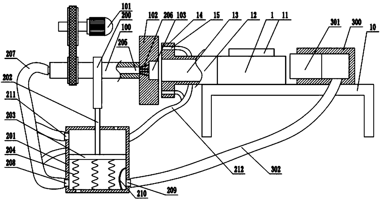
[0031] The reference numerals in the accompanying drawings of the specification include: the turbine shell 1, the air inlet end 11, the air outlet end 12, the cavity 13, the boss 14, the installation hole 15, the workbench 10, the horizontal shaft 100, the motor 101, the grinding wheel 102, Groove 103, cam 200, cylinder 201, piston rod 202, piston 203, spring 204, through hole 205, dust suction hole 206, dust suction pipe 207, the first air intake check valve 208, air outlet check valve 209, anti Dust net 210 , second air intake check valve 211 , branch pipe 212 , air pump 300 , positioning block 301 , exhaust pipe 302 .

[0032] Such as figure 1 Shown is an embodiment of the present invention, which discloses a turbine casing end face grinding device, which includes a frame, a workbench 10, a grinding unit, a dust removal unit, and a pressing unit, and the grinding unit and the pre...


PUM


Abstract

The invention relates to the technical field of grinding equipment, and particularly discloses a turbine shell end surface grinding device. The device comprises a grinding unit, a dust suction unit and an abutting unit; the grinding unit comprises a horizontal shaft, the end part of the horizontal shaft is connected with a grinding disc, and the grinding disc is provided with a groove; the dust suction unit comprises an air cylinder and a cam, the cam is fixed on the horizontal shaft, a piston rod of the air cylinder abuts against the periphery of the cam, a spring is fixedly arranged below anair cylinder piston, an air outlet one-way valve and a first air inlet one-way valve are arranged on the side wall of the air cylinder, a through hole is formed in the horizontal shaft, a dust suction hole is formed in a grinding wheel, the horizontal shaft is connected with a dust suction pipe, the dust suction pipe communicates with the first air inlet one-way valve, a branch pipe communicatingwith the dust suction pipe is further arranged, and the branch pipe is inserted into a mounting hole of a turbine shell; and the abutting unit comprises an inflator, a positioning block is slidably connected in the inflator, the air outlet one-way valve is connected with an exhaust pipe, and the exhaust pipe communicates with the inflator. By adopting the technical scheme, scrap iron can be cleared at the same time in the grinding process, so that manual cleaning is not needed.

Description

technical field [0001] The invention relates to the technical field of grinding equipment, in particular to a grinding device for a turbine casing end face. Background technique [0002] The turbine casing is an important part of the turbocharger. As the external firmware of the turbocharger, its main function is to form the working cavity of the turbine, guide the incoming and outgoing airflow, and support the turbine shaft and turbine rotating components. An integrally fixed base. [0003] The structure of the turbine shell usually includes an air inlet, an air outlet, and an internal cavity. In order to facilitate the connection of pipes, the end faces of the air outlet and the air inlet of the turbine shell are uniformly cast with bosses, and mounting holes are opened around the bosses. Since the turbine is Working under high temperature and high speed conditions requires the turbine shell to be made of superalloy. In addition, due to the complex shape of the turbine sh...

Claims


Application Information

Patent Timeline
Patent Type & Authority Applications(China)
IPC IPC(8): B24B7/16B24B55/06B24B41/06
CPCB24B7/16B24B41/06B24B55/06
Inventor 印义胜
Owner 重庆市乐珐机电有限责任公司
Why Eureka
Try Eureka