Prefabricated hybrid structure prefabricated toilet and manufacturing method thereof

A hybrid structure and prefabricated technology, applied in the direction of building structure, building components, special buildings, etc., can solve the problems of inconsistent concrete integrity, soft steel structure, horizontal displacement, etc., to save labor and steel usage Consumption, good anti-leakage performance, guarantee the effect of quality control

Active Publication Date: 2018-10-02
重庆宜府住工科技有限公司
View PDF6 Cites 2 Cited by
  • Summary
  • Abstract
  • Description
  • Claims
  • Application Information

AI Technical Summary

Problems solved by technology

[0002] In recent years, the construction of green, energy-saving and healthy buildings has become our basic national policy. Due to the good plasticity and toughness of steel, it can have large deformation, can withstand dynamic loads well, and is easy to assemble. Therefore, domestic steel structure prefabricated buildings, steel Structural concrete hybrid structures are widely used in various building systems, but the steel structure is too soft and prone to large horizontal displacements. Leakage of toilets due to large displacements during use is a pain point for all prefabricated buildings at present.
The current prefabricated building toilets are all on-site construction and pouring concrete technology, which cannot keep up with the development of building industrialization, and the assembled structural components are inconsistent with the integrity of the cast-in-place concrete. It is urgent to find a toilet with a higher degree of assembly and guarantee A new type of prefabricated toilet with its own structure and the firmness and reliability of the connection with beams and other components, and at the same time improving the installation speed

Method used


Image

  • Prefabricated hybrid structure prefabricated toilet and manufacturing method thereof
  • Prefabricated hybrid structure prefabricated toilet and manufacturing method thereof
  • Prefabricated hybrid structure prefabricated toilet and manufacturing method thereof

Examples


Embodiment 1

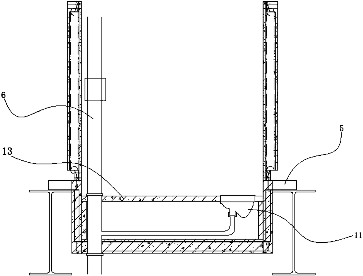
[0059] This embodiment discloses a mixed-structure prefabricated toilet for prefabricated buildings, see figure 1 and figure 2 , floor elements and wall elements fixedly connected to steel beams or composite beams.

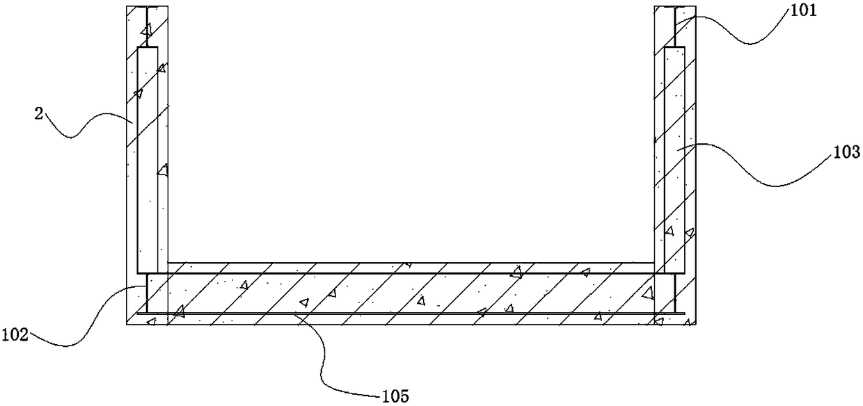
[0060] see image 3 , Figure 4 and Figure 5, the bottom plate unit is a prefabricated steel skeleton concrete sinking groove type prefabricated installation unit. The base plate unit includes a base plate steel skeleton 1 , concrete 2 and a reinforcement mesh 3 . The floor steel framework 1 includes four upper beams 101 , four lower beams 102 , steel framework side vertical bars 103 and floor beams 105 . The four lower side rails 102 are arranged in a rectangular shape. The floor beam 105 is arranged between the two opposite side rails 102 . The four roof beams 101 are arranged in a rectangle, and each roof beam 101 has a protruding part. The protruding part of the roof side beam 101 is provided with a connecting piece I5. The upper side rail 101 is ar...

Embodiment 2

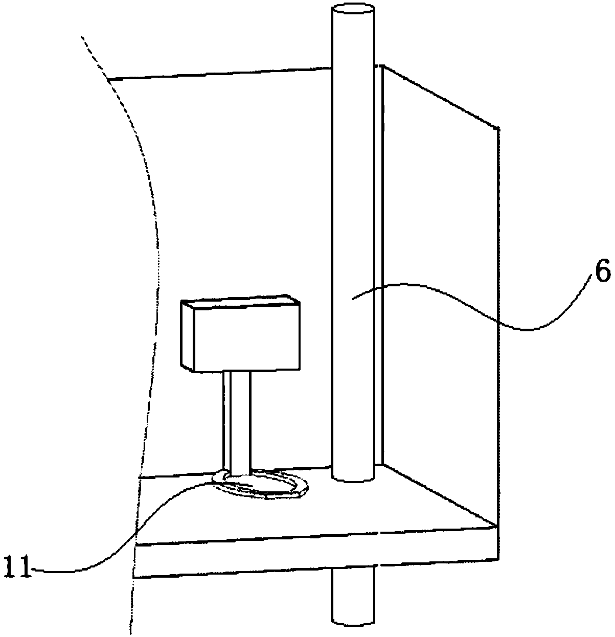
[0064] This embodiment discloses a mixed-structure prefabricated toilet for prefabricated buildings, including a wall unit, a sewage main riser 6, and a floor unit fixedly connected with steel beams or composite beams.

[0065] The base plate unit includes a base plate steel skeleton 1 , concrete 2 and a reinforcement mesh 3 . The floor steel framework 1 includes four upper beams 101 , four lower beams 102 , steel framework side vertical bars 103 and floor beams 105 . The steel used for the base plate steel frame 1 is I-beam, channel steel, angle steel, C-beam, Z-beam or welded H-beam. The four lower side rails 102 are arranged in a rectangular shape. The floor beam 105 is arranged between the two opposite side rails 102 . The four roof beams 101 are arranged in a rectangle, and each roof beam 101 has a protruding part. The protruding part of the roof side beam 101 is provided with a connecting piece I5. The upper side rail 101 is arranged above the lower side rail 102 . ...

Embodiment 3

[0070] This embodiment discloses a method for manufacturing the prefabricated toilet described in Embodiment 1 or 2, comprising the following steps:

[0071] 1) Carry out scheme design as required.

[0072] 2) The floor unit is prefabricated at the factory.

[0073] 2.1) Prefabricated floor steel skeleton 1.

[0074] 2.2) Weld the connecting plate I4 and the connecting piece I5 on the steel frame 1 of the bottom plate.

[0075] 2.3) Arrange the reinforcement mesh 3.

[0076] 2.4) According to the appearance size and function requirements of the floor steel skeleton 1, the steel formwork of the toilet floor unit is produced in batches.

[0077] 2.5) Put the finished base plate steel frame 1 into the steel mold box, and hoist it to the vibrating table of the processing plant.

[0078] 2.6) In addition to the reserved pouring area, pour impermeable concrete or waterproof concrete and expansive concrete in sequence, and then start the vibrating table to make the unit concrete ...


PUM


Abstract

The invention provides a hybrid structure prefabricated toilet for a prefabricated building and a manufacturing method thereof. The toilet comprises a wall unit, a sewage main riser, and a bottom plate unit fixedly connected with a steel beam or a superposed beam. During operation, the bottom plate unit is fixedly connected with the steel beam or the superposed beam through connecting pieces I. The bottom plate unit is connected with a floor through cast-in-place nodes. A wallboard is fixedly connected with the bottom plate unit through the matching of a connecting plate II and a correspondingconnecting plate I. The sewage main riser penetrates through and is fixedly connected to the bottom plate unit. The manufacturing method of the toilet includes the steps of scheme design, prefabricating the bottom plate unit, prefabricating the wallboard, transportation to the site, assembling and pouring floors and the like. The toilet can reduce construction difficulties caused by weather changes, is convenient and quick to install, and has good anti-leakage performance.

Description

technical field [0001] The invention relates to the field of building construction, and mainly relates to a prefabricated mixed-structure assembled toilet and a manufacturing method thereof. Background technique [0002] In recent years, the construction of green, energy-saving and healthy buildings has become our basic national policy. Due to the good plasticity and toughness of steel, it can have large deformation, can withstand dynamic loads well, and is easy to assemble. Therefore, domestic steel structure prefabricated buildings, steel Structural concrete hybrid structures are widely used in various building systems, but steel structures are too flexible and prone to large horizontal displacements. Toilet leakage caused by large displacements during use is a pain point for all prefabricated buildings at present. The current prefabricated building toilets are all on-site construction and pouring concrete technology, which cannot keep up with the development of building i...

Claims


Application Information

Patent Timeline
IPC IPC(8): E04H1/12E04B2/56
CPCE04B2/56E04H1/1266
Inventor 欧应
Owner 重庆宜府住工科技有限公司
Why Eureka
Try Eureka