
Hydraulic-electric combined space thruster

A combination of space and thruster technology, applied in thrust reversers, jet propulsion devices, machines/engines, etc., can solve problems such as inability to meet the requirements of low-orbit missions, and achieve the effect of reducing the total mass

Active Publication Date: 2018-10-02
DALIAN INST OF CHEM PHYSICS CHINESE ACAD OF SCI
View PDF6 Cites 7 Cited by
  • Summary
  • Abstract
  • Description
  • Claims
  • Application Information

AI Technical Summary

Problems solved by technology

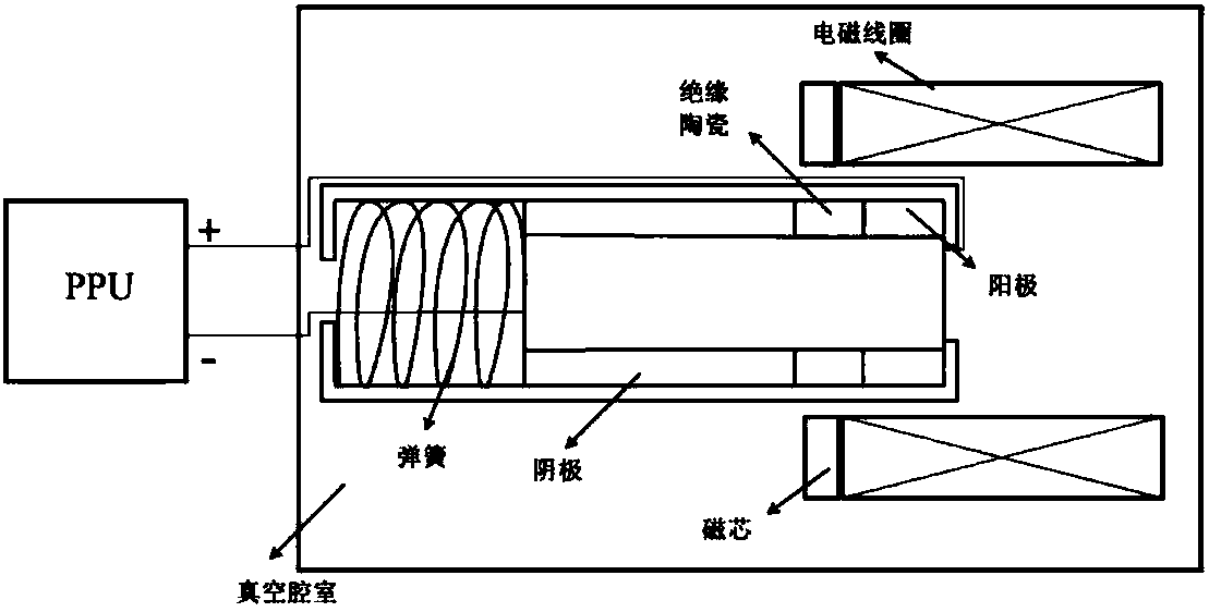
However, as a branch of the plasma thruster, the thrust provided by this type of thruster is on the order of micronewtons, which cannot meet the requirements of low-orbit missions.

Method used


Image

  • Hydraulic-electric combined space thruster
  • Hydraulic-electric combined space thruster
  • Hydraulic-electric combined space thruster

Examples


Embodiment Construction

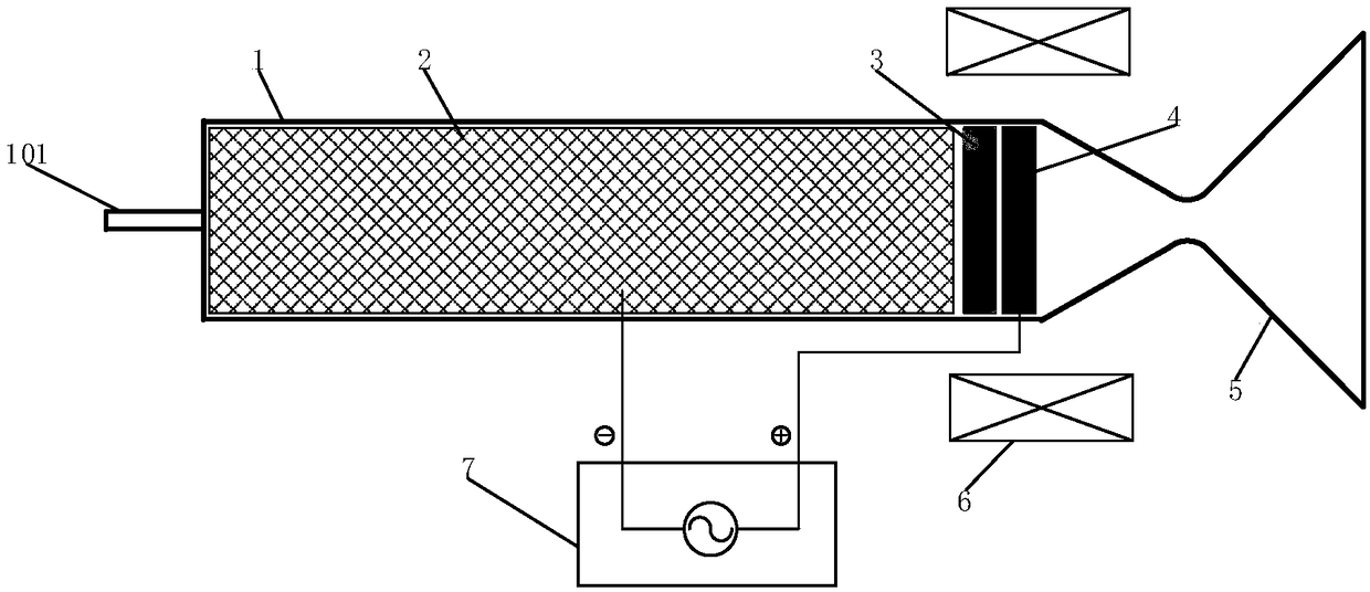
[0024] Such as image 3 As shown, when the aircraft performs a low-orbit mission, the aircraft requires the attitude and orbit control engine to provide a thrust between 1N-20N. At this time, the liquid propellant passes through figure 1 The middle propellant inlet 101 enters the catalyst loading area, and the propellant is decomposed into high-temperature and high-pressure gas under the action of the catalyst. After passing through the porous insulator 3 and the anode 4, the gas expands and accelerates under the action of the nozzle to generate the target thrust. This process converts the internal energy of the propellant into kinetic energy. When the aircraft performs high-orbit or deep-space exploration missions, the aircraft requires attitude and orbit control to provide a specific impulse between 1000s and 3000s. image 3 The medium 7 power supply generates a pulse voltage of 800V, and the surface of the catalyst particles close to the anode in the combustion chamber wil...


PUM


Abstract

The invention discloses a hydraulic-electric combined space thruster, comprising a combustion chamber, a catalyst, an insulator, an anode, a sprayer nozzle, a permanent magnet ring and a power supplysystem. Catalyst particles are filled in a combustion chamber. A circular through hole is formed between two end faces of the insulator, and the insulator is installed in the combustion chamber and ison downstream of the catalyst (along the flow direction of a propellant, the same below). Geometric profile of the anode is the same with that of the insulator, and the anode is installed in the combustion chamber and is on downstream of the insulator. The sprayer nozzle is connected with the tail of the combustion chamber. The permanent magnet ring is nested on the tail end outside the combustion chamber. The positive pole of the power supply system is connected with the anode, and a negative pole is connected with the catalyst. A liquid rocket engine and a plasma rocket engine are integrated in one hydraulic-electric combined space thruster, so that one engine has two working modes. When an aircraft executes low orbit tasks, the aircraft works by using a combustion propellant (chemicalenergy of the propellant is converted into kinetic energy). When the aircraft performs high-orbit or deep-space exploration missions, the aircraft uses plasma propulsion to work (converts kinetic energy of a power source into kinetic energy), so that one thruster can meet different mission requirements of the aircraft, thereby reducing total mass of a spacecraft.

Description

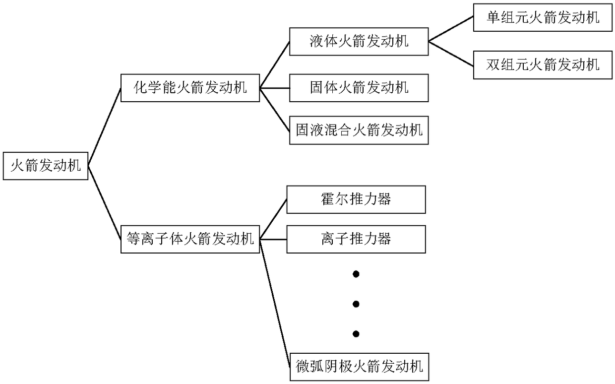
technical field [0001] The invention relates to the technical field of spacecraft engines, in particular to a combined hydraulic-electric space thruster for aircraft attitude and orbit control. Background technique [0002] Since October 4, 1957, when the former Soviet Union launched the first artificial earth satellite, human beings have never stopped exploring space. From the Apollo moon landing program to the Curiosity Mars rover, from the International Space Station to Tiangong-2, scientists from all over the world have explored this mysterious universe with continuous innovation. [0003] The rapid development of the aerospace industry is inseparable from the support of space propulsion technology. After decades of development, space propulsion technology can basically meet the needs of various space missions. As a technology developed on the basis of rocket propulsion, space propulsion can be divided into four categories according to the nature of the mission: launch,...

Claims


Application Information

Patent Timeline
Patent Type & Authority Applications(China)
IPC IPC(8): F02K9/42F02K9/74F03H1/00
CPCF02K9/42F02K9/74F03H1/0081
Inventor 郝剑昆尹艳辉
Owner DALIAN INST OF CHEM PHYSICS CHINESE ACAD OF SCI
Learn More