
Atmospheric visibility measurement method and device through lidar

An atmospheric visibility and lidar technology, applied in measurement devices, radio wave measurement systems, climate sustainability, etc., can solve the problems of not considering the influence of atmospheric molecules, inability to measure visibility, low measurement accuracy, etc., to improve measurement accuracy and The effect of stability, reducing volume and improving measurement accuracy

Pending Publication Date: 2018-10-09
CHENGDU UNIV OF INFORMATION TECH
View PDF16 Cites 16 Cited by
  • Summary
  • Abstract
  • Description
  • Claims
  • Application Information

AI Technical Summary

Problems solved by technology

[0003] Traditional visibility measuring instruments have low measurement accuracy in rainy, hazy, snowy and other weather environments, while lidar has the advantages of high precision, less environmental impact, and flexible detection angles. The slope method and the Klett inversion method are mostly used to deduce the atmospheric extinction coefficient
The slope method is mainly aimed at the weather conditions with a relatively clear and uniform atmosphere; the Klett inversion method is suitable for the situation of a non-uniform atmosphere, but the Klett method does not consider the influence of atmospheric molecules
[0004] In addition, the traditional visibility measurement equipment mainly includes two types of transmission-type visibility meter and forward-scattering visibility meter. Ship-borne, airborne and other occasions; the distance between the transmitting and receiving ends of the forward-scattering visibility meter is usually about one meter, so it can only measure the meteorological visibility in a local area, and it can only be extended to a wide area under the assumption that the atmosphere is uniformly distributed
In addition, these two types of visibility meters usually can only measure the meteorological visibility in the horizontal direction, and cannot measure the slope or the visibility in the vertical direction required by applications such as aircraft takeoff and landing or bombing and skydiving.

Method used


Image

  • Atmospheric visibility measurement method and device through lidar
  • Atmospheric visibility measurement method and device through lidar
  • Atmospheric visibility measurement method and device through lidar

Examples


Embodiment 1

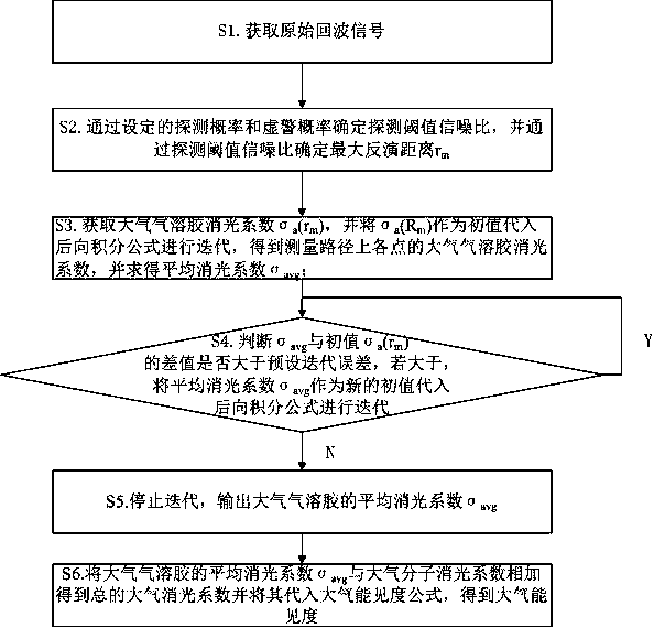
[0033] Such as figure 1 As shown, a laser radar atmospheric visibility measurement method can rely on a laser radar atmospheric visibility measurement device, and can also be implemented independently, including the following steps:

[0034] S1. Obtain the original echo signal, and calculate the number N(r) of atmospheric echo photons.

[0035] S2. Set the detection probability and false alarm probability, determine the detection threshold signal-to-noise ratio through the set detection probability and false alarm probability, and determine the maximum inversion distance r through the detection threshold signal-to-noise ratio m .

[0036] S3. Get the maximum inversion distance r m Atmospheric aerosol extinction coefficient σ at a (r m ), and σ a (R m ) as the initial value is substituted into the backward integral formula to iterate to obtain the atmospheric aerosol extinction coefficient of each point on the measurement path, and average all the obtained atmospheric aer...

Embodiment 2

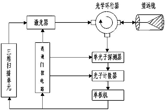
[0058] Such as figure 2 As shown, a lidar atmospheric visibility measurement device includes a laser transceiver unit, a photon detection and acquisition unit, a system control and data processing unit, and a three-dimensional scanning unit. The laser transceiver unit includes a laser, an optical circulator and a telescope, and a photon detection and acquisition unit. The unit includes a single photon detector and a photon counter, the system control and data processing unit includes a gate control circuit and a single board computer, the output end of the laser is connected to the first end of the optical circulator, and the second end of the optical circulator is connected to the telescope connection, the optical circulator is set on the optical path between the laser and the telescope, the third end of the optical circulator is connected to the input end of the single photon detector, the output end of the single photon detector is connected to the input end of the photon c...


PUM


Abstract

The invention discloses an atmospheric visibility measurement method through a lidar, and the method comprises the following steps: obtaining an original echo signal; determining a detection thresholdsignal to noise ratio, and determining the maximum inversion distance through the detection threshold signal to noise ratio; obtaining an atmospheric aerosol extinction coefficient, taking the atmospheric aerosol extinction coefficient as an initial value, substituting the atmospheric aerosol extinction coefficient into a backward integration formula for iteration to obtain the atmospheric aerosol extinction coefficient of each point on a measurement path, and solving the mean extinction coefficient; judging whether the difference between the mean extinction coefficient and the initial valueis greater than a preset iteration error or not: taking the mean extinction coefficient as a new initial value if the difference between the mean extinction coefficient and the initial value is greater than the preset iteration error, and substituting the mean extinction coefficient into the backward integration formula for iteration, or else stopping the iteration and outputting the mean extinction coefficient; adding the mean extinction coefficient to an atmospheric molecule extinction coefficient to obtain the total atmospheric extinction coefficient, and substituting the total atmosphericextinction coefficient into an atmospheric visibility formula to obtain the atmospheric visibility. The method effectively improves the measurement precision of the atmospheric visibility, and also improves the measurement stability of the atmospheric visibility in different atmospheric environments.

Description

technical field [0001] The invention relates to the technical field of atmospheric monitoring, in particular to a laser radar atmospheric visibility measurement method and device. Background technique [0002] In recent years, with the rapid development of industrialization, urbanization and the automobile industry, the problem of air pollution has become more and more prominent. The phenomenon of "smog" weather raging on the land of China has caused great troubles to people's lives, and also to China's The international image had a very bad influence. Atmospheric visibility is an important parameter of air pollution, and its effective measurement is of great significance. [0003] Traditional visibility measuring instruments have low measurement accuracy in rainy, hazy, snowy and other weather environments, while lidar has the advantages of high precision, less environmental impact, and flexible detection angles. The slope method and the Klett inversion method are mostly ...

Claims


Application Information

Patent Timeline
Patent Type & Authority Applications(China)
IPC IPC(8): G01S7/48G01S7/481G01S17/95
CPCG01S7/4802G01S7/481G01S17/95Y02A90/10
Inventor 何修军
Owner CHENGDU UNIV OF INFORMATION TECH
Learn More