Cornea measuring method and system
A corneal measurement and corneal technology, used in eye testing equipment, medical science, diagnosis, etc., can solve problems such as the inability to measure the corneal refractive index and the inability to obtain corneal thickness, and achieve high-precision results
- Summary
- Abstract
- Description
- Claims
- Application Information
AI Technical Summary
Problems solved by technology
Method used
Image
Examples
Embodiment 1
[0035] Embodiment 1 of the present invention: a kind of corneal measuring method, such as Figure 9 As shown, first, optical coherence tomography is used to measure the optical path L0 from the front surface of the cornea to the back surface; secondly, the focus lens is moved, when the focus of the probe light is on the front and back surfaces of the cornea, the signal intensity is the maximum value, and the current When the focal point of the probe light is located on the front and rear surfaces of the cornea, the distance L1 between the two corresponding positions of the focusing lens; finally, the refractive index and corneal thickness of the cornea are obtained using ray tracing technology.
[0036] Obtaining the refractive index and corneal thickness of the cornea by using the ray tracing technique may specifically include the following steps:
[0037] a. According to the optical path of the detection arm, use ray tracing technology (existing technology) to establish the ...
Embodiment 2
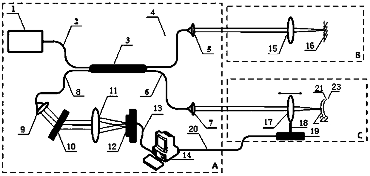
[0048] Embodiment 2: realize a kind of corneal measurement system of the method described in embodiment 1, such as figure 1 As shown, it includes: a low-coherence light interference and signal processing device A, a reference arm B and a detection arm C, and the low-coherence light interference and signal processing device A includes: a low-coherence light source 1, a first optical fiber 2, and a beam splitter 3 , second optical fiber 4, first optical fiber collimator 5, third optical fiber 6, second optical fiber collimator 7, fourth optical fiber 8, fourth lens 9, grating 10, third lens 11, linear array CCD 12, Cables 13 and computer 14; the reference arm B includes: a first lens 15 and a reflector 16, the low-coherent light source 1 is connected to the beam splitter 3 through the first optical fiber 2, and the beam splitter 3 is connected to the second optical fiber 4 Connected with the first fiber collimator 5, the optical splitter 3 is connected with the second optical fi...
Embodiment 3
[0050] Embodiment 3: realize a kind of corneal measurement system of the method described in embodiment 1, such as Figure 10 As shown, it includes: a low-coherent light interference and signal processing device A, a reference arm B and a detection arm C. The low-coherent light interference and signal processing device A includes: a low-coherent light source 1, a beam splitter 3, a first optical fiber standard Collimator 5, the second fiber collimator 7, the fourth lens 9, grating 10, the third lens 11, linear array CCD 12, cables 13 and computer 14; the reference arm B includes: the first lens 15 and Mirror 16, the low-coherent light source 1 is connected to the beam splitter 3, the beam splitter 3 is connected to the first fiber collimator 5, the beam splitter 3 is connected to the second fiber collimator 7, and the beam splitter 3 makes the detection light and The reference light passes through the fourth lens 9, the grating 10, and the third lens 11 successively, and is im...
PUM
 Abstract
Description
Claims
Application Information
 - R&D
- Intellectual Property
- Life Sciences
- Materials
- Tech Scout
- Unparalleled Data Quality
- Higher Quality Content
- 60% Fewer Hallucinations
Browse by: Latest US Patents, China's latest patents, Technical Efficacy Thesaurus, Application Domain, Technology Topic, Popular Technical Reports.
© 2025 PatSnap. All rights reserved.Legal|Privacy policy|Modern Slavery Act Transparency Statement|Sitemap|About US| Contact US: help@patsnap.com


