Method for promoting electrochemical trapping of low-concentration CO2 through membrane electrolysis
A low-concentration, membrane electrolysis technology, applied in chemical instruments and methods, separation methods, separation of dispersed particles, etc., can solve the problem of high theoretical power consumption
- Summary
- Abstract
- Description
- Claims
- Application Information
AI Technical Summary
Problems solved by technology
Method used
Image
Examples
example 1
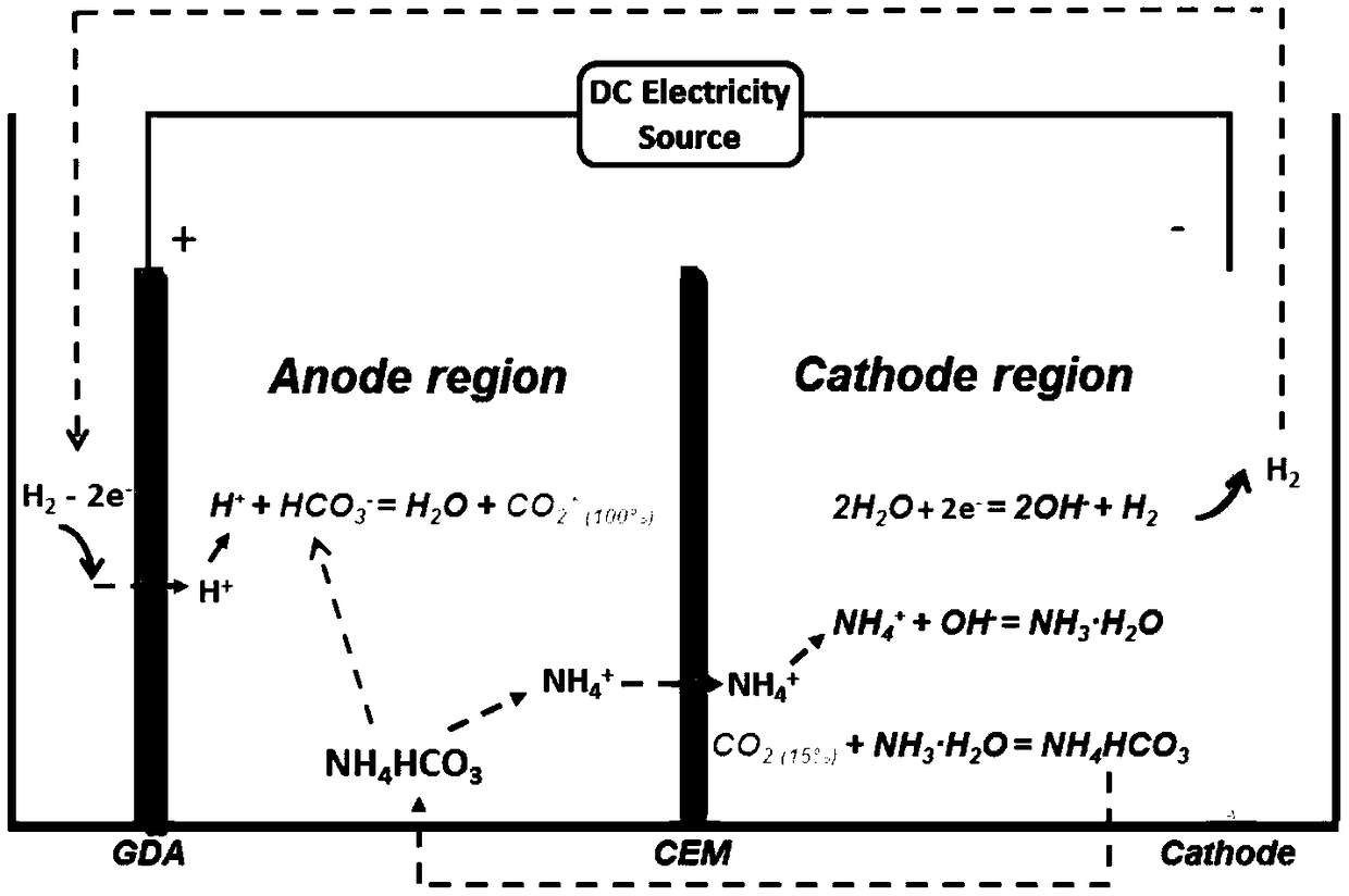
[0061] The cation exchange membrane Nafion115 membrane is placed in the electrolyzer and the electrolyzer is divided into a cathode area and an anode area, and the anolyte (1M (NH 4 ) 2 SO 4 +1MNH 4 HCO 3 ) and catholyte (1M(NH 4 ) 2 SO 4 ) is placed in a 200mL airtight storage tank, and the pump circulates between the electrolyzer device and the storage tank at a flow rate of 20mL / min, and 10mL / min of H is introduced into the anode area 2 . A DC power supply was applied between the anode electrode and the cathode electrode, the electrolysis reaction was powered by an external DC power supply (IT6932A, Itech), and the temperature of the electrolytic cell was 50°C.
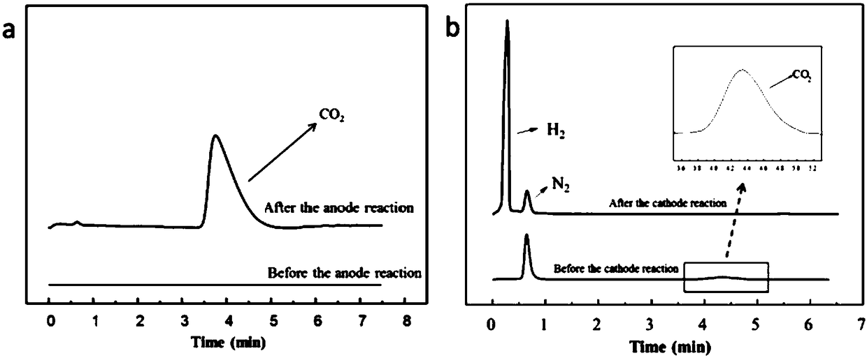
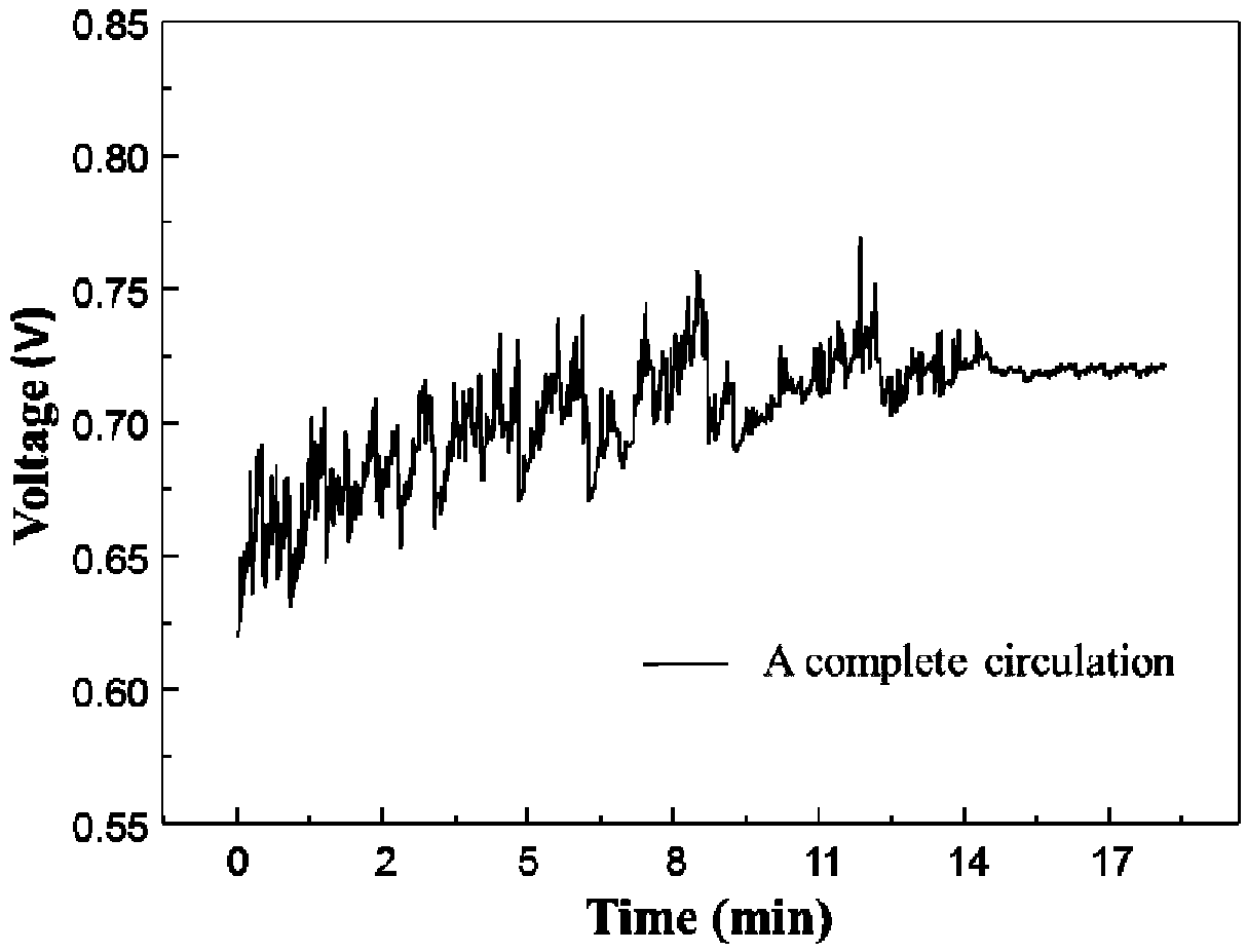
[0062] Set the current density to 40mA / m 2 , and constantly monitor and record the voltage change law of the electrolyzer. During the electrolysis process, 20mL / min of argon gas is passed into the anolyte storage tank to desorb the CO in the anolyte. 2 Carried to the gas chromatograph to verify that the d...
example 2
[0075] Anolyte (1.5M (NH 4 ) 2 SO 4 +1.5MNH 4 HCO 3 ) and catholyte (1.5M (NH 4 ) 2 SO 4 ) placed in a 200mL airtight storage tank, circulated between the electrolyzer device and the storage tank at a flow rate of 15mL / min through a pump, and 10mL / min of H 2 . A DC power supply was applied between the anode electrode and the cathode electrode, the electrolysis reaction was powered by an external DC power supply (IT6932A, Itech), and the temperature of the electrolytic cell was 55°C.
[0076] Set the current density to 20mA / m 2 , the electrolysis voltage at this time is 0.53V. Therefore, the calculation according to formula (7) shows that: adopting the scheme of this embodiment, theoretically, every ton of CO captured electrochemically 2 The energy consumption is only 322.885kW h. During the electrolysis process, 20mL / min of argon gas is passed into the anolyte storage tank to desorb the CO in the anolyte. 2 Carried to the gas chromatograph to verify that the desorb...
example 3
[0079] Anolyte (2M(NH 4 ) 2 SO 4 +2MNH 4 HCO 3 ) and catholyte (2M(NH 4 ) 2 SO 4 ) is placed in a 200mL closed storage tank, and the pump circulates between the electrolyzer device and the storage tank at a flow rate of 10mL / min, and 15mL / min of H 2 . A DC power supply was applied between the anode electrode and the cathode electrode, the electrolysis reaction was powered by an external DC power supply (IT6932A, Itech), and the temperature of the electrolytic cell was 45°C.
[0080] Set the current density to 10mA / m 2 , the electrolysis voltage at this time is 0.45V. Therefore, the calculation according to formula (7) shows that: adopting the scheme of this embodiment, theoretically, every ton of CO captured electrochemically 2 The energy consumption is only 274.148kW h. During the electrolysis process, 20mL / min of argon gas is passed into the anolyte storage tank to desorb the CO in the anolyte. 2 Carried to the gas chromatograph to verify that the desorbed CO 2 ...
PUM
 Abstract
Description
Claims
Application Information
 - R&D
- Intellectual Property
- Life Sciences
- Materials
- Tech Scout
- Unparalleled Data Quality
- Higher Quality Content
- 60% Fewer Hallucinations
Browse by: Latest US Patents, China's latest patents, Technical Efficacy Thesaurus, Application Domain, Technology Topic, Popular Technical Reports.
© 2025 PatSnap. All rights reserved.Legal|Privacy policy|Modern Slavery Act Transparency Statement|Sitemap|About US| Contact US: help@patsnap.com


