Icing adhesion strength testing device

A technology of adhesion strength and testing device, applied in the direction of measuring device, mechanical device, instrument, etc., can solve the problems of difficult operation, complicated equipment, uncertain position of ice breaking, etc., and achieve good repeatability.

Inactive Publication Date: 2018-10-12
CRRC QINGDAO SIFANG CO LTD
View PDF11 Cites 12 Cited by
  • Summary
  • Abstract
  • Description
  • Claims
  • Application Information

AI Technical Summary

Problems solved by technology

However, this method has disadvantages such as uncertain location of ice cube fracture, difficulty in calculating the actual adhesion area, complex equipment, and difficult operation.

Method used


Image

  • Icing adhesion strength testing device
  • Icing adhesion strength testing device
  • Icing adhesion strength testing device

Examples


Embodiment 1

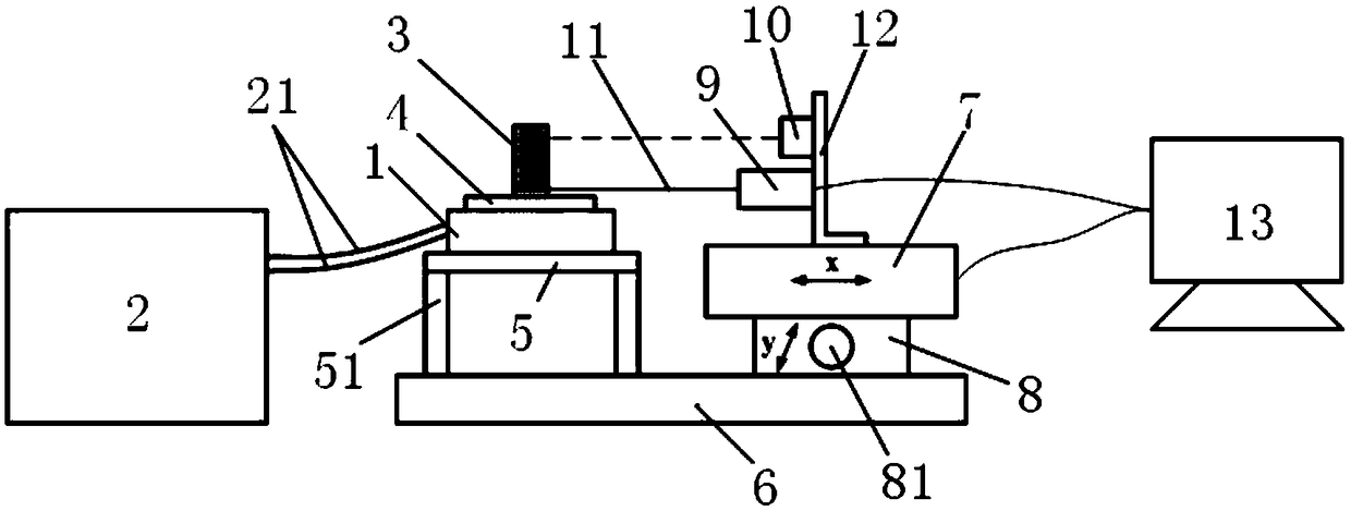
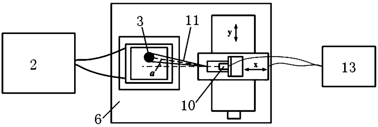
[0045] In embodiment 1 of the present invention, as Figure 1-2 As shown, the load measuring element is a tension gauge 9. When applying tension, keep the axial direction of the tension gauge 9 at the same height as the center plane of the connecting rope sleeve 11 and the axial direction of the tension gauge 9 is at the same height as The central axis of the sleeve 3 is in the same vertical plane to ensure the accuracy of the test results.

[0046] In order to facilitate the adjustment of the axial displacement of the tension gauge 9, one side of the cold table 1 is provided with a lateral movement platform 7 that can drive the tension gauge 9 to move along its axial direction (X direction), and the tension gauge 9 passes through the support 12 is installed on the described lateral movement platform 7.

[0047] Specifically, the bracket 12 is a right-angle bracket 12, and the right-angle bracket 12 includes a horizontal section and a vertical section, the horizontal section ...

Embodiment 2

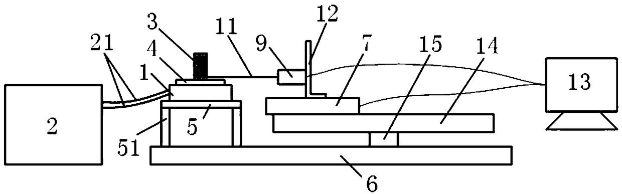
[0054] Such as Figure 3-4 As shown, the difference between Embodiment 2 and Embodiment 1 is that the longitudinal moving platform 8 is replaced by a turntable 14 that can freely rotate around the z-axis. Specifically, a rotatable turntable 14 is provided below the horizontal moving platform 7, so The center of the turntable 14 is connected to the base 6 through a vertically arranged rotating shaft 15; the axial direction of the tension gauge 9, the centerline of the turntable 14 and the central axis of the sleeve 3 are located in the same vertical plane . An electric translation platform is installed at the edge of the turntable 14, so that the projection line of the axis of the tension meter 9 in the horizontal plane passes through the center of the turntable, and at the same time, it is ensured that the connection point where the wire rope is wrapped on the tension meter 9 within the entire movement amount of the electric translation platform P does not cross the center of...

Embodiment 3

[0056] In this example, if Figure 5-6 As shown, the load-measuring element is a torque sensor 17, and the torque sensor 17 is arranged on a turntable 16. This embodiment adopts an electric turntable 16, and the center of the turntable 16 is located above the torque sensor 17. There is a roller 18 that can rotate with the rotating table 16, and the torque sensor 17 is connected with the connecting rope 11 through the roller 18, and is used for retracting the connecting rope 11. One end of the connecting rope 11 is connected to the The wheel edges of the rollers 18 are connected tangentially. Adjust the installation height of the roller 18 so that the central symmetrical plane of the roller 18 is at the same height as the center plane of the draw groove 31 of the sleeve 3; One end is fixed on the roller 18; the rotation speed and angle of rotation of the electric rotary table 16 are set through a computer program, the electric rotary table 16 is started, and the steel wire rop...


PUM


Abstract

The invention relates to the field of icing adhesion strength testing,and discloses an icing adhesion strength testing device. The icing adhesion strength testing device comprises a cooling table,a cooling circulator,a sleeve,a part to be tested and a force testing element. The cooling circulator is connected with the cooling table through a refrigerant circulating pipeline,the part to be tested is fixed to the cooling table,and the upper end and the lower end of the sleeve are open. A pull groove is formed in the circumferential direction of at least one end of the sleeve,the end,provided with the pull groove,of the sleeve is arranged on the part to be tested,and liquid is injected into the sleeve and cooled into an icicle through the cooling table; one end of an element with force to betested is connected with a connecting rope sleeve,the connecting rope sleeve is sleeved with the pull groove of the sleeve,the element with the force to be tested exerts pull force to the sleeve through the connecting rope sleeve until the icicle is separated from the surface of the part to be tested,and the icing adhesion strength between the icicle and the part to be tested is calculated. The icing adhesion strength testing device is easy,convenient and fast to operate,and good in result repeatability.

Description

technical field [0001] The invention relates to the technical field of ice coating adhesion strength testing, in particular to an ice coating adhesion strength testing device. Background technique [0002] At present, domestic and foreign scientific research institutions (including some paint companies) mostly use the ice-coated adhesion strength of the coating to evaluate the ice-phobic performance of the coating. However, there is no consensus on the test methods for coating ice adhesion strength, and each uses different test devices and test methods. [0003] At present, quantitative liquid water droplets are used to drop on the surface of the refrigerated test piece to make it freeze naturally, and then use a sliding knife with a force sensor that slides parallel to the plane of the test piece to peel off the icing convex hull tangentially, and record the peeling process. The maximum tangential force, this value is used to characterize the ice adhesion force on the surf...

Claims


Application Information

Patent Timeline
Patent Type & Authority Applications(China)
IPC IPC(8): G01N19/04
CPCG01N19/04
Inventor 张金煜崔健杨中林曹建刚刘韶庆
Owner CRRC QINGDAO SIFANG CO LTD
Why Eureka
Try Eureka