Super-clean treatment process system for flue gas

A process system and flue gas technology, applied in the direction of gas treatment, dispersed particle filtration, membrane technology, etc., can solve the problems that performance is greatly affected by load fluctuations, high resistance, and low dust removal efficiency of pre-dust collectors, etc., to achieve low overall resistance, The effect of long equipment life and light weight

Pending Publication Date: 2018-10-16
宁波国电龙高科环境工程技术有限公司
View PDF2 Cites 3 Cited by
  • Summary
  • Abstract
  • Description
  • Claims
  • Application Information

AI Technical Summary

Problems solved by technology

[0006] The purpose of the present invention is to solve the existing SCR denitrification system performance is greatly affected by load fluctuations, high resistance, low dust removal efficiency of the pre-dust collector, and the need to add a second-stage dust removal equipment before the induced draft fan to achieve ultra-clean emissions. Furthermore, a flue gas ultra-clean treatment process system is provided

Method used


Image

  • Super-clean treatment process system for flue gas
  • Super-clean treatment process system for flue gas

Examples


specific Embodiment approach 1

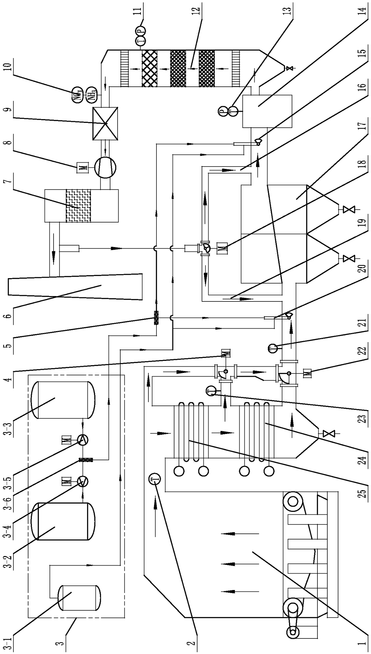
[0026] Specific implementation mode one: combine figure 1 Describe this embodiment, a flue gas ultra-clean treatment process system of this embodiment, which includes a flue temperature adjustment system, a dust collector 17, a disturbance device 14, an SCR reactor 12, a waste heat recovery system, an induced draft fan 8, an ultra-clean desulfurization Dust removal equipment 7, reducing agent system and automatic control system, flue temperature adjustment system, dust collector 17, SCR reactor 12, waste heat recovery system, induced draft fan 8 and ultra-clean desulfurization and dust removal equipment 7 are connected in sequence from front to back, reducing agent One end of the system is connected to the inlet of the dust collector 17, the other end of the reducing agent system is connected to the inlet of the SCR reactor 12, and the disturbance device 14 is set at the inlet of the SCR reactor 12;

[0027] The smoke temperature regulating system includes a high-temperature h...

specific Embodiment approach 2

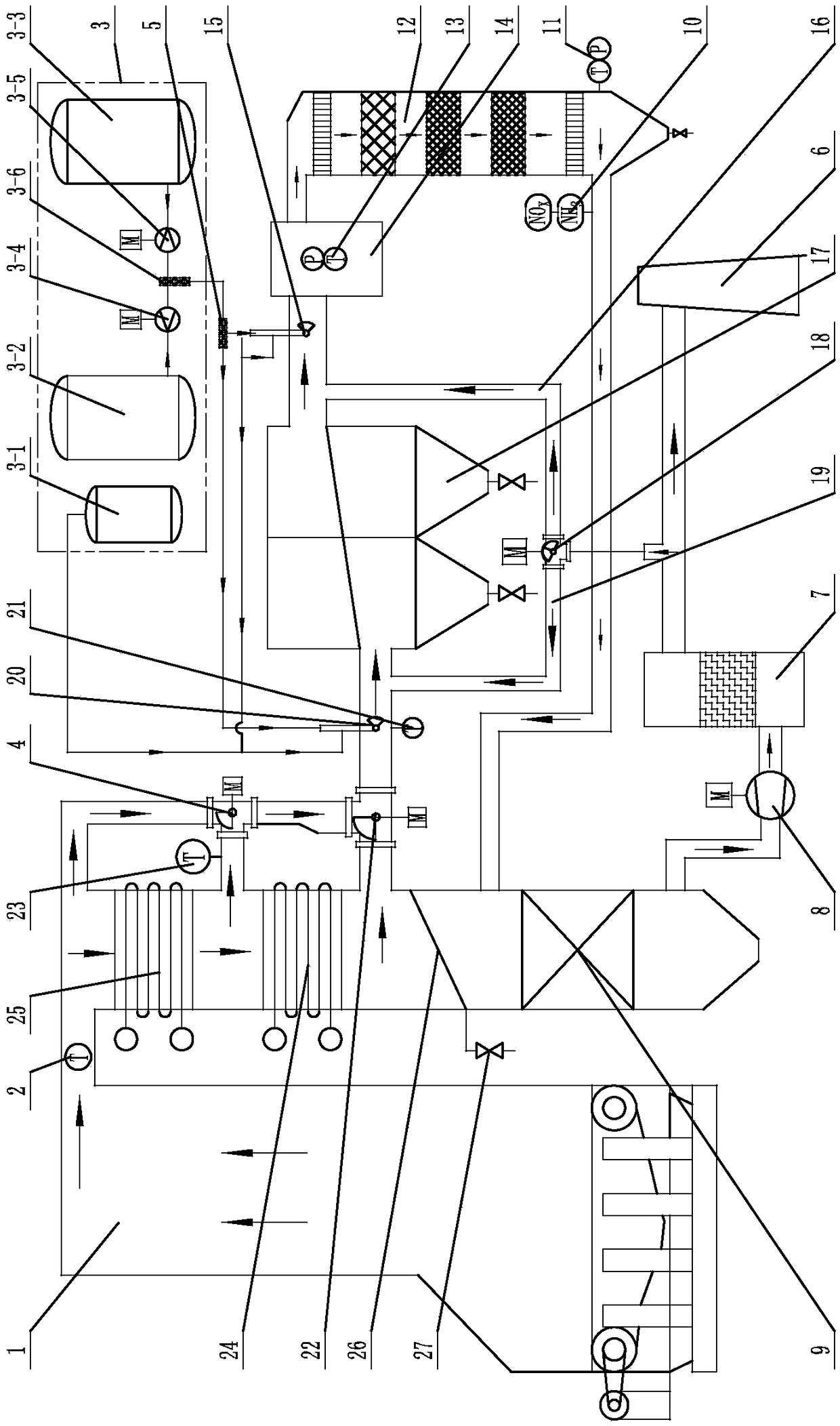
[0029] Specific implementation mode two: combination figure 2Describe this embodiment. This embodiment also includes an anti-dust system. The medium-temperature heat exchange surface 24 communicates with the waste heat recovery system through a flue, and the anti-dust system is arranged between the medium-temperature heat exchange surface 24 and the waste heat recovery system. The low-temperature flue (the first low-temperature bypass 19 and the second low-temperature bypass 16) is drawn from the outlet of the ultra-clean desulfurization and dust removal equipment 7, and there is no need to install a fan. When the temperature is too high, open the low-temperature three-way valve 18 to mix the low-temperature flue gas into the high-temperature flue gas. The mixing position is controlled by the second thermocouple 23. It is mixed before the agitator 14 through the second low-temperature bypass 16 , otherwise, it is mixed before the dust collector 17 through the first low-temper...

specific Embodiment approach 3

[0030] Specific implementation mode three: combination figure 1 and figure 2 Describe this embodiment. The anti-ash system of this embodiment includes ash discharge partition 26, ash discharge pipeline 27 and ash cooling equipment. The ash discharge partition 26 is arranged obliquely between the medium-temperature heat exchange surface 24 and the waste heat recovery system. On the flue wall of the flue, a through hole is opened on the flue wall at the lower end of the ash discharge partition 26, and one end of the ash discharge pipeline 27 communicates with the through hole on the flue wall, and the other end of the ash discharge pipeline 27 is connected to the ash discharge pipeline. The slag cooling equipment or kiln 1 is connected. In this way, the anti-dust system is mainly used for the transformation of the original boiler economizer or the waste heat boiler of the kiln. An inclined wear-resistant and heat-resistant insulation is installed between the upper and lower he...


PUM


Abstract

The invention discloses a super-clean treatment process system for flue gas, relates to the field of super-clean emission treatment of flue gas from industrial boilers and kilns and solves the problems that performance of the existing SCR denitration system is greatly affected by load fluctuation, resistance is higher, dust removal efficiency of a pre-dedusting device is low, and secondary dust removal equipment needs to be added in front of an induced draft fan to realize super-clean emission. The super-clean treatment process system comprises a smoke temperature regulating system, a dust remover, an SCR reactor, a waste heat recovery system, an induced draft fan and super-clean desulfurization dust removal equipment which are sequentially connected from front to back, one end of a reducing agent system is communicated with an inlet of the dust remover, the other end of the reducing agent system is communicated with an inlet of a disturber, the disturber is arranged at an inlet of theSCR reactor, a first thermocouple is arranged at an inlet of a high-temperature heat exchange surface, a second thermocouple is arranged at an outlet of the high-temperature heat exchange surface, and a third thermocouple is mounted between an outlet of a medium-temperature three-way valve and the dust remover. The process system is used for realizing super-clean flue gas emission denitration treatment of first dust removal and later smoke removal treatment.

Description

technical field [0001] The invention relates to the field of ultra-clean emission treatment of flue gas from industrial boilers and kilns, and in particular to a process system for ultra-clean treatment of flue gas. Background technique [0002] As the country pays more and more attention to environmental protection, more and more regions have become more and more strict on the emission of air pollutants from boilers. In some regions, the emission of industrial boilers has been implemented in accordance with the ultra-clean emission standards of thermal power plants. [0003] The denitrification technologies that can realize the ultra-clean emission of nitrogen oxides mainly include oxidation method and SCR. Among them, the oxidation method has obvious secondary pollution and the operating cost is too high. The denitrification technology with technical and economic feasibility is mainly SCR. [0004] The ash contained in the coal itself or the ash generated during the kiln p...

Claims


Application Information

Patent Timeline
Patent Type & Authority Applications(China)
IPC IPC(8): B01D53/86B01D53/56B01D46/30B01D46/00
CPCB01D53/8631B01D46/00B01D46/30B01D2258/0283
Inventor 姜志华马伟王帅杜大全王强吴燕燕张岩孙国禹
Owner 宁波国电龙高科环境工程技术有限公司
Why Eureka
Try Eureka