Traction wheel structure

A traction wheel and composite material layer technology, applied in the field of elevator traction wheels, can solve the problems of large wear, uneven wear, and increased cost of the traction rope, and achieve stable and reliable driving, high wear resistance, and lightening effect of weight

Pending Publication Date: 2018-10-16
HANGZHOU HUNING ELEVATOR PARTS CO LTD
View PDF9 Cites 1 Cited by
  • Summary
  • Abstract
  • Description
  • Claims
  • Application Information

AI Technical Summary

Problems solved by technology

However, the service life of increasing the equivalent friction coefficient through the groove type is limited, and a larger friction coefficient cannot be obtained, nor can it improve the safety and life of the whole machine from the traction drive system, and reduce the system cost and other practical problems.
[0004] On the other hand, due to the inconsistent tension of the traction rope (belt), it is easy to cause inconsistent wear of the rope groove (or the contact surface of the traction belt), and undue serious uneven wear occurs, thereby changing the shape of the groove and seriously affecting the traction. Rope (belt) life and traction, bring a greater safety risk to the elevator
In the actual operation of the existing elevator, the traction rope (belt) wears a lot, and needs to be replaced every five years on average, which further increases the cost

Method used


Image

  • Traction wheel structure
  • Traction wheel structure

Examples


Embodiment 1

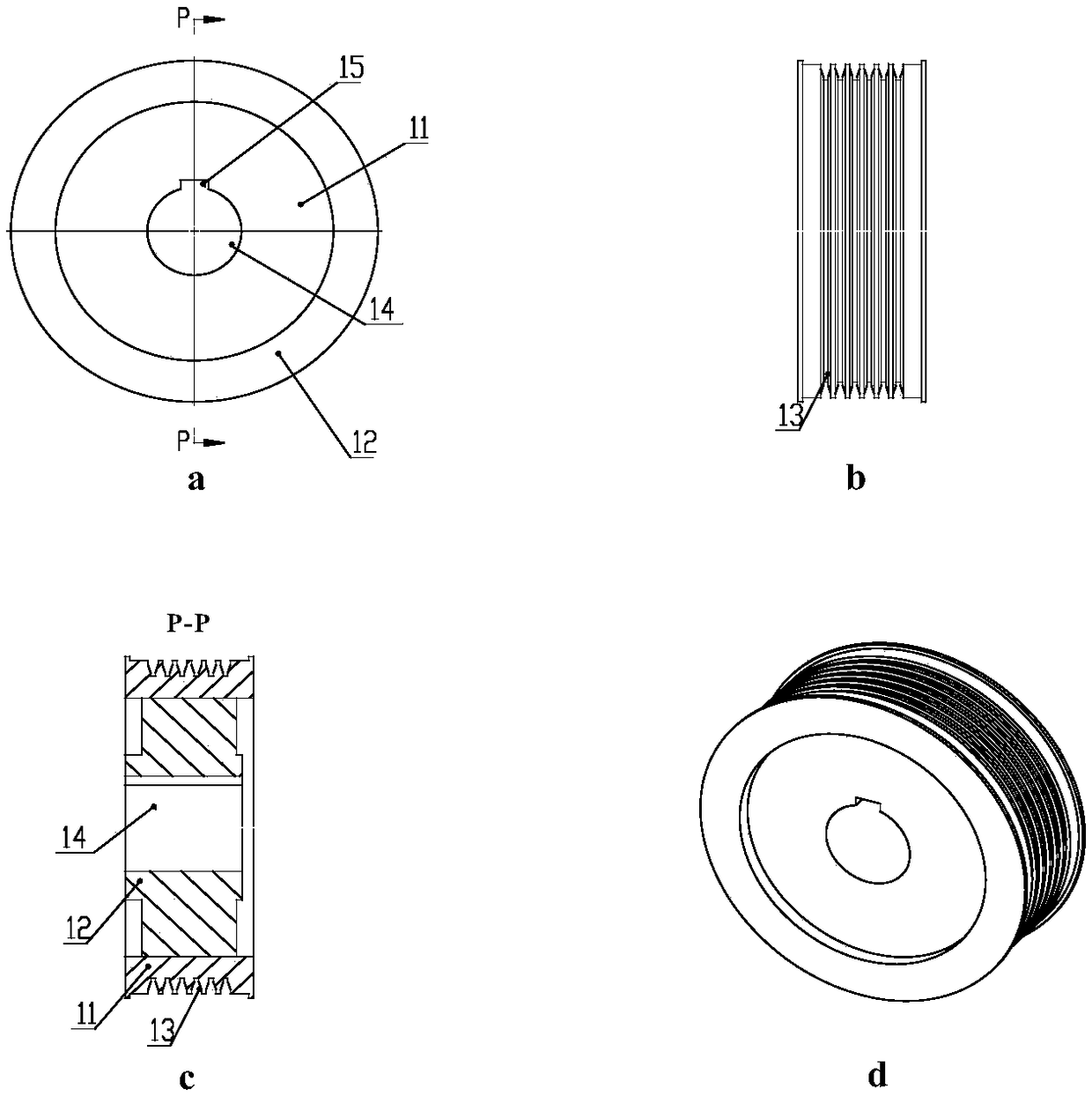
[0033] Such as figure 1 As shown in (a-d), a single-layer composite material layer traction sheave structure includes:

[0034] The traction sheave connector 11 and the composite material layer 12, the composite material layer 12 is arranged on the outer circular working surface of the traction sheave body 11, and a traction sheave groove 13 is formed on the composite material layer 12; the traction sheave connector 11 has a shaft The hole 14 and the shaft hole 14 are provided with a spline groove 15 .

[0035] The composite material layer 12 is a single layer. The traction sheave connecting body 11 can be made of steel material, and the composite material layer 12 can be made of carbon fiber, or can be made of steel matrix composite carbon fiber through non-chemical treatment.

Embodiment 2

[0037] The only difference between this embodiment and Embodiment 1 is that: the traction sheave surface is formed on the composite material layer 12, and the traction sheave surface is formed by pressing the composite material layer 12 and then heat-treated. The traction belts work together to form a traction system. For other descriptions of the structure of the traction sheave, refer to the first embodiment above, which will not be repeated here.

[0038] In the traction sheave structure described in Embodiments 1 and 2, the existing traction groove or traction surface is directly set on the traction sheave connecting body, and an additional layer of composite material is added on the traction sheave connecting body, Set up a traction groove or traction surface on the composite material layer, which can reduce production costs, and can also choose to design the physical and mechanical properties such as the type, strength, and hardness of the composite material, and at the ...

Embodiment 3

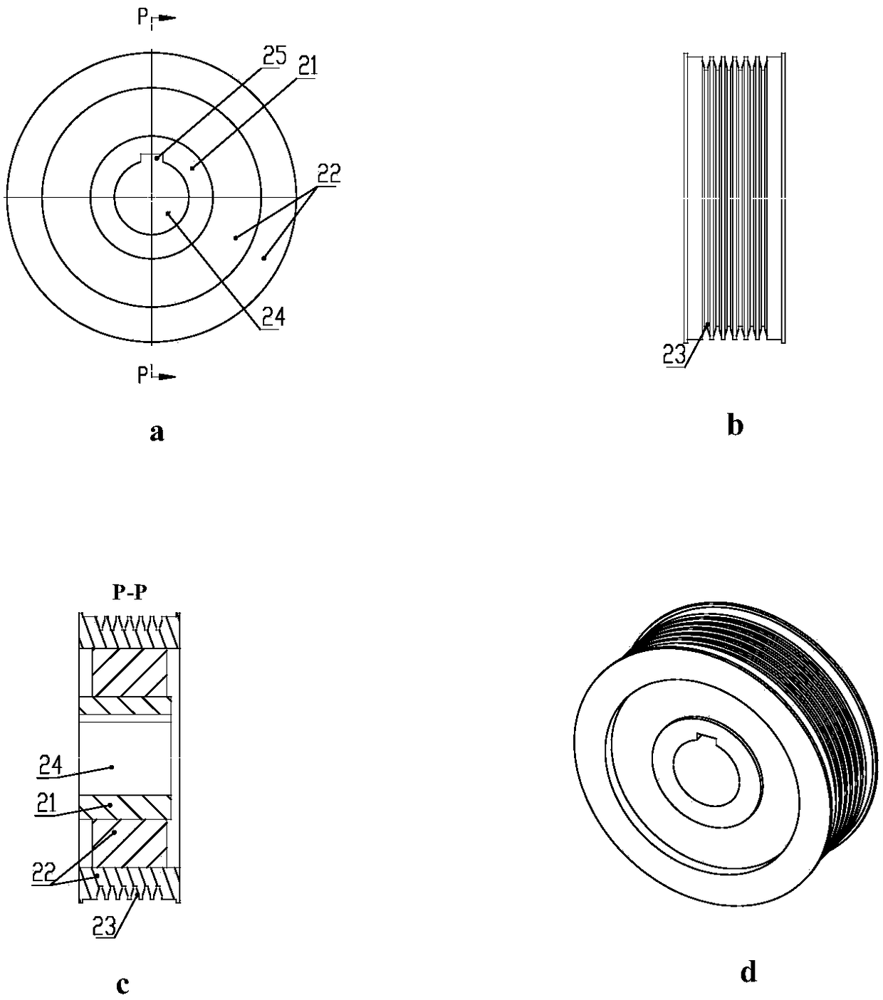
[0040] Such as figure 2 As shown in (a-d), a traction sheave structure with double-layer composite material layers includes:

[0041] The traction wheel connector 21 and the composite material layer 22, the composite material layer 22 is arranged on the outer circular working surface of the traction wheel connector 21, the composite material layer 22 is a double layer, on the outer composite material layer of the composite material layer 22 A traction wheel groove 23 is formed; the traction wheel connecting body 21 has a shaft hole 24 , and a spline groove 25 is provided on the shaft hole 24 . The types of each layer of composite material layers can be the same or different, determined according to actual requirements. The traction sheave connecting body 21 can be made of steel material, and the double-layer composite material layer 22 can be made of carbon fiber and aramid fiber, and can also be made of metal matrix composite material and non-metallic composite material, an...


PUM


Abstract

The invention provides a traction wheel structure which comprises a traction wheel connecting body provided with an outer circle working face. The traction wheel connecting body is made of a metal material. The traction wheel structure is characterized by further comprising a composite material layer. The composite material layer is arranged on the outer circle working face of the traction wheel connecting body and forms a traction wheel groove or a traction wheel face. In an existing traction system, abrasion to the contact face between a traction rope or a traction belt and a traction rope groove or a traction belt is inconsistent, the phenomenon of severe uneven abrasion is usually caused, the life of the traction rope or the traction belt and the traction wheel is influenced, the safety risk is brought to an elevator, and the cost is high. According to the traction wheel structure, the equivalent friction coefficient of the surface of the traction wheel can be improved remarkably,comprehensive properties of abrasion resistance, strength, toughness and the like are improved, the diameter of the traction wheel rope or the traction belt and the traction wheel is reduced, the weight of the traction system is reduced, and the miniaturization design of the elevator traction system and the whole elevator is achieved.

Description

technical field [0001] The invention relates to a traction wheel structure, which is applied in the field of elevator traction wheels. Background technique [0002] The traction sheave is a key component of the elevator traction machine. The traction force driven by the traction sheave to drive the elevator is generated by the friction between the traction rope (belt) and the traction sheave groove (or traction sheave surface). The shape and state changes of the rope groove and surface of the pulley will directly affect the size of the traction force and the life of the traction rope (belt), and its quality will directly affect the safety performance and service life of the traction. [0003] Since the traction sheave carries all the dynamic and static loads of the elevator car, load capacity, counterweight and other devices, and is the source of determining the function of the traction drive system and the whole machine, the traction sheave is required to have high strength...

Claims


Application Information

Patent Timeline
Patent Type & Authority Applications(China)
IPC IPC(8): B66B11/08
CPCB66B11/08
Inventor 邹家春姚荣康王伟孟红星李密
Owner HANGZHOU HUNING ELEVATOR PARTS CO LTD
Why Eureka
Try Eureka