
Device for detecting pressure of water in concrete pipe

A detection device, concrete pipe technology, applied in the direction of measuring device, using stable tension/pressure test material strength, instruments, etc., can solve the problems of heavy operation of detection device, heavy pipe body, time-consuming and labor-intensive, etc., to promote health The effect of developing, ensuring the test effect and shortening the test time

Pending Publication Date: 2018-10-16
ZHENGZHOU NO 1 CONSTR ENG GRP
View PDF7 Cites 4 Cited by
  • Summary
  • Abstract
  • Description
  • Claims
  • Application Information

AI Technical Summary

Problems solved by technology

[0004] After the pipe is paved in place, it has the characteristics of one-time molding and lifetime use. Once the engineering quality accident is caused by the water seepage of the pipe or other quality problems, it will cause unimaginable social impact.
This puts forward requirements for the quality inspection of reinforced concrete pipes. The current national and industry standards have not yet put forward specific requirements for pipe quality inspection devices, and various regions and inspection centers have not reached a consensus. At present, only a horizontal internal water pipe has been regulated. Pressure detection device and a vertical internal water pressure detection device, there is no further detailed description of the detection device itself, the detection device commonly used in the market is cumbersome to operate, requires a lot of auxiliary equipment and personnel to work, time-consuming and labor-intensive, today's reinforced concrete pipe specifications There are more and more, and the size is getting bigger and bigger. In the construction of large-scale mechanical pipe jacking, the pipe diameter even reaches 3 to 4m, and the weight of the pipe body is getting bigger and bigger. This poses a great challenge to the test and detection auxiliary equipment.

Method used


Image

  • Device for detecting pressure of water in concrete pipe
  • Device for detecting pressure of water in concrete pipe
  • Device for detecting pressure of water in concrete pipe

Examples


Embodiment 1

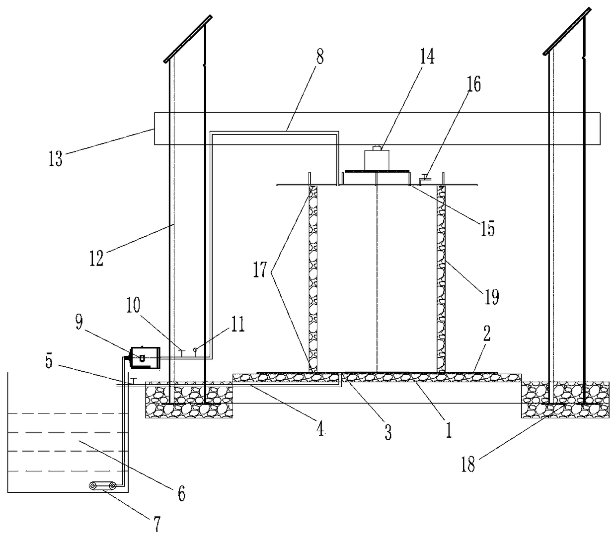
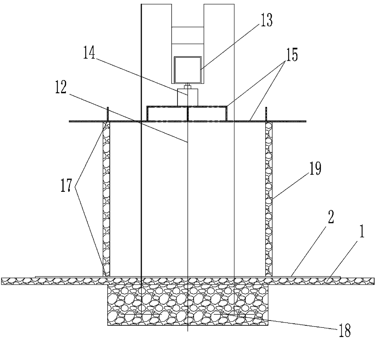
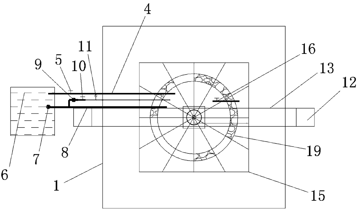
[0019] Embodiment 1: as Figure 1-3 The water pressure detection device in the concrete pipe shown is composed of two parts. The first part is the pipe base system, including steel column 12, steel column 12 foundation, steel beam 13, device cap 1, plugging device 15, rubber seal Circle 17, concrete pipe, jack 14 totally eight members. The second part is the device frame, which is stabilized by the steel column 12, the foundation of the steel column 12, the steel beam 13 and the device platform 1 to ensure the safety and stability of the detection process; the blocking device 15 is composed of two horizontal steel plates and ribbed steel plates The structure is specially customized to ensure that the plugging equipment does not deform and does not leak air; the jack 14 acts on the plugging device 15 through the reverse force of the steel beam 13, and squeezes the seam between the pipe and the steel plate to the minimum, and the role of the rubber sealing ring 17 In order to e...

Embodiment 2

[0026] Embodiment 2: another kind of water pressure detection device in concrete pipes, including bearing mechanism and high-pressure water supply mechanism, etc., such as figure 1 with figure 2 The bearing mechanism shown includes a column foundation 18 , a device platform 1 and a platform steel liner 2 . Wherein, the bearing platform 1 of the device and the steel lining plate 2 of the bearing platform are compounded to form a bearing platform of the reinforced concrete pipe 19, and the column foundation 18 is located at symmetrical positions on both sides of the bearing platform.

[0027] The upper side of each side column foundation 18 is fixed with a steel column 12, and the tops of the steel columns 12 on both sides are distributed with sockets and fitted with a rear steel beam 13, and the lower center of the steel beam 13 is vertically connected with a jack 14, and the lower end of the jack 14 is connected with a The plugging device 15 is provided with an exhaust hole ...

Embodiment 3

[0033] Embodiment 3: on the basis of embodiment 2, the rubber seal ring adopted is an annular rubber air bag. At this time, the upper and lower rubber air bags are provided with inflation valves, and the upper and lower rubber air bags contact the reinforced concrete pipe 19 up and down and are filled by inflation. The inner and outer sides of the upper and lower ends of the reinforced concrete pipe 19.


PUM


Abstract

The invention discloses a device for detecting the pressure of water in a concrete pipe. The device comprises a bearing mechanism and a high pressure water supply mechanism, sockets are distributed atthe top ends of steel columns on the two sides respectively, and the steel columns are sleeved with a rear steel cross beam; a jack is perpendicularly connected with the center of the lower portion of the steel cross beam, an opening plugging device is connected with the lower end of the jack, and an air vent and a water inlet are formed in the opening plugging device; and a water reservoir is arranged, a water pump is mounted, and after a water outlet of the water pump is sequentially connected with a pressure pump, a water inlet valve and a pressure meter through a high pressure water inletpipe, the tail end of the water pump is fixed to the water inlet of the opening plugging device in a sealing mode. An opening plugging steel plate is high in strength, not prone to deforming, can plug tightly, and thus the test effect is guaranteed. The device for detecting the pressure of water in the concrete pipe is convenient to mount and dismount, quick and convenient, the test time is shortened, the working efficiency is improved, and the test cost is lowered. The device replaces the operation procedures of a traditional detection device, reduces the investment of labor force and material sources, promotes the health development of scientific test and detection industries, and provides a powerful basis for scientific research.

Description

Technical field: [0001] The invention belongs to the field of building construction and test and detection technology, and in particular relates to a water pressure detection device in a concrete pipe. Background technique: [0002] Reinforced concrete pipes are widely used in urban rainwater and sewage construction, farmland water conservancy construction, electric power and railway engineering construction, and comprehensive pipe gallery construction, among which urban construction consumes the most. [0003] With the continuous acceleration of urbanization, the scale of infrastructure projects under construction is getting larger and larger, and the application of reinforced concrete pipes in rainwater and sewage projects is becoming more and more extensive. According to incomplete statistics, the current domestic annual production capacity of reinforced concrete pipes is 40,000- Between 60,000 kilometers, according to different construction methods, it is divided into re...

Claims


Application Information

Patent Timeline
Patent Type & Authority Applications(China)
IPC IPC(8): G01N3/02G01N3/12
CPCG01N3/02G01N3/12Y02A20/00
Inventor 张栋梁张峰山时媛媛蒋丽楠张会伍李华徐德远周国杰
Owner ZHENGZHOU NO 1 CONSTR ENG GRP
Learn More