Spraying and scattering tower device

A spray pipe and tower body technology, which is applied in the field of waste gas treatment equipment, can solve the problems of large resistance of the diffuser tube insertion depth system, the depth of the diffuser tube insertion depth in the flue gas corridor, and low desulfurization and dust removal efficiency, so as to reduce the risk of scaling , increase the residence time, weaken the effect of scouring

Pending Publication Date: 2018-10-19
SOUTH CHINA UNIV OF TECH
View PDF7 Cites 5 Cited by
  • Summary
  • Abstract
  • Description
  • Claims
  • Application Information

AI Technical Summary

Problems solved by technology

The scattering device with openings in the wall of the scattering tube has problems such as the large insertion depth of the scattering tube resulting in high system resistance, and the insufficient insertion depth of the scattering tube is likely to form a "smoke corridor" and cause low desulfurization and dust removal efficiency.
Although the diffuser has improved this problem to a certain extent, there are still problems such as uneven distribution of bubbles that are not conducive to mass transfer when the flue gas flow rate is too high

Method used


Image

  • Spraying and scattering tower device
  • Spraying and scattering tower device

Examples


Embodiment

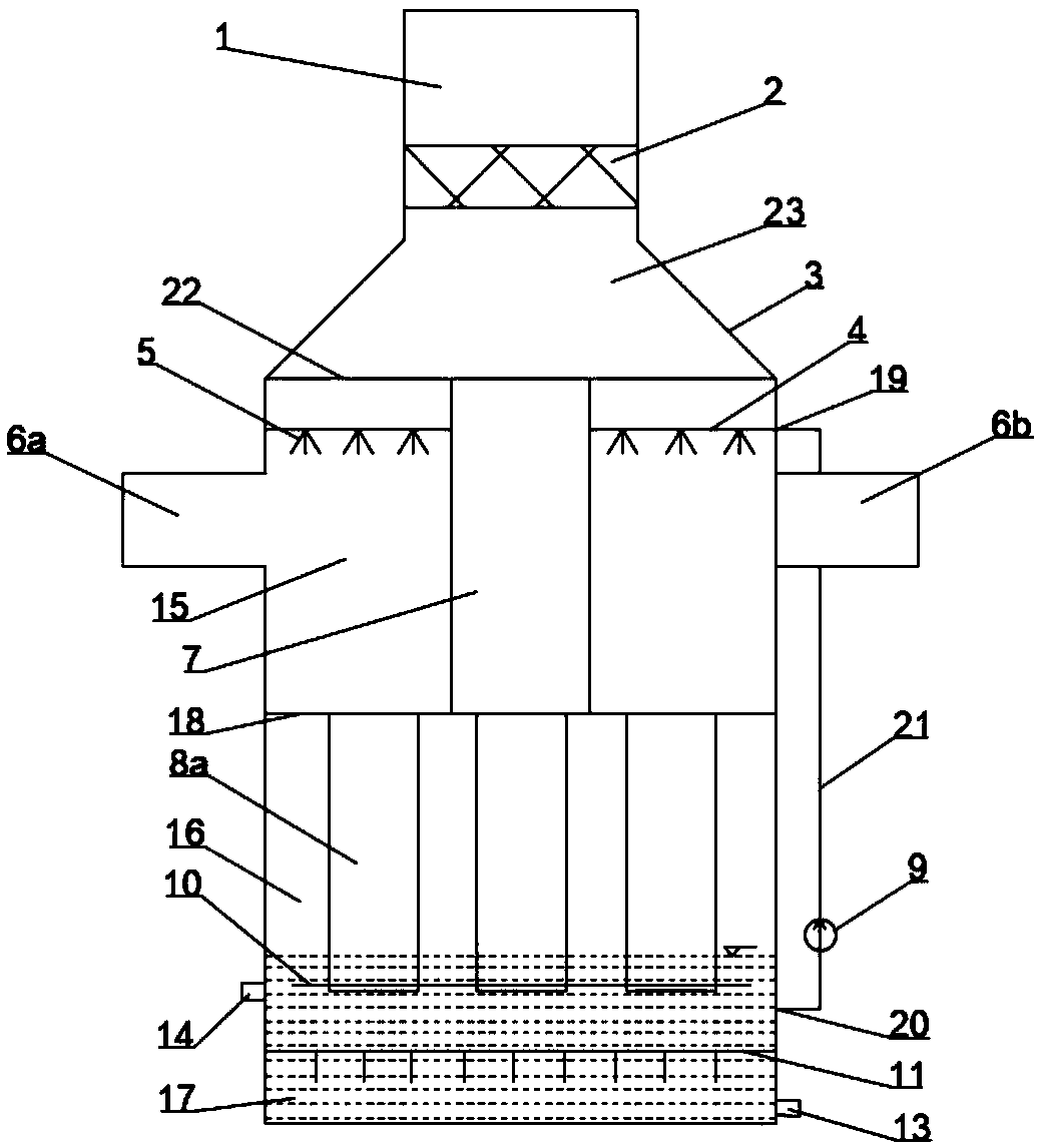
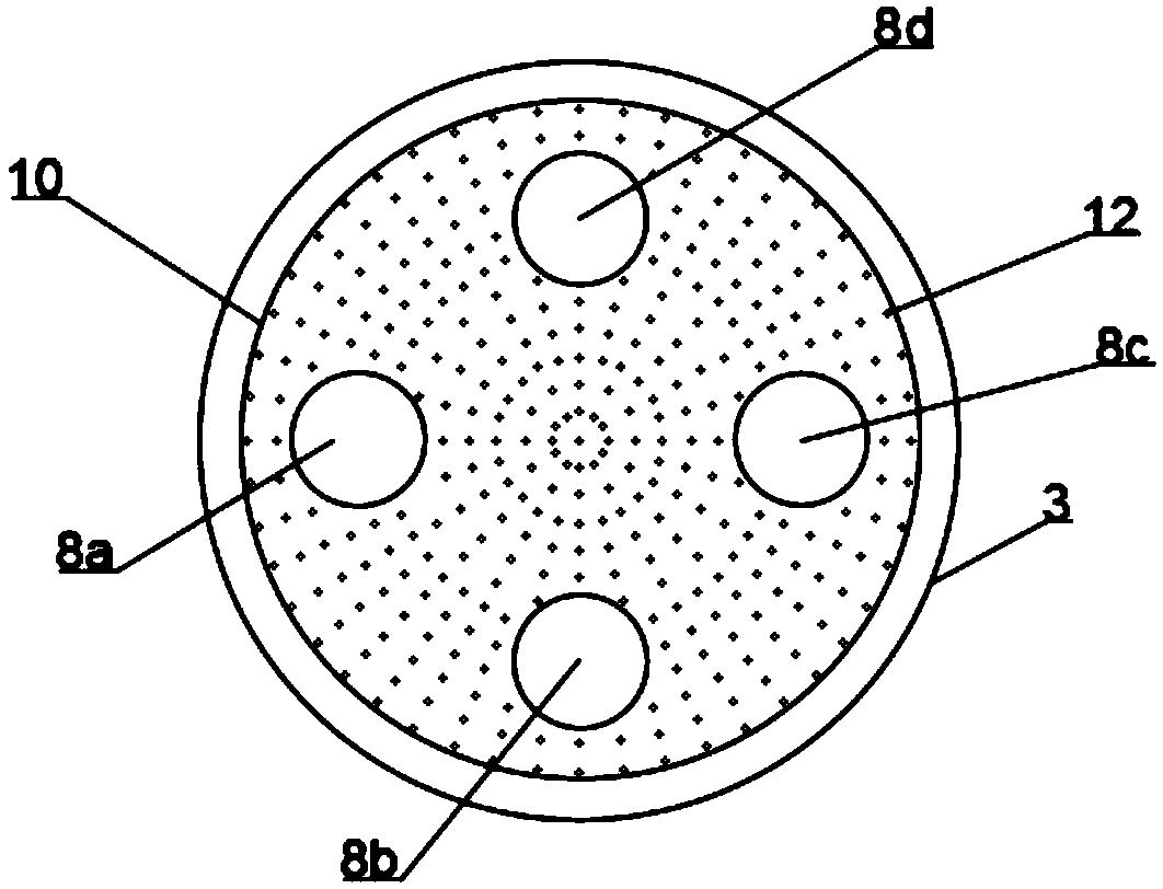
[0024] Such as figure 1 and figure 2 As shown, a spray scattering tower device includes an outlet flue 1 and a cylindrical tower body 3, with the outlet flue 1 as the upper end, and is set between the outlet flue 1 and the cylindrical tower body 3 Demister 2, and the three are connected;

[0025] The interior of the cylindrical tower body 3 includes an upper bin 23, a spraying middle bin 15, a bubbling lower bin 16, and a slurry pool 17 at the bottom; An upper isolation baffle 22 and a lower isolation baffle 18 are respectively arranged between them, and these two baffles are sealed and connected with the periphery of the cylindrical tower body 3; The first inlet flue 6a and the second inlet flue 6b are horizontally arranged opposite each other, and the spray pipe 4, the nozzle 5, and the ascending flue 7 coaxial and in the center are arranged inside the spray chamber 15; The isolating baffle 22 and the lower isolating baffle 18 are sealed and connected with the ascending ...


PUM


Abstract

The invention discloses a spraying and scattering tower device. The spraying and scattering tower device comprises an exit pipeline, a defogger and a cylindrical tower body, wherein the interior of the cylindrical tower body comprises an upper bin, a spraying middle bin, an air bubbling lower bin and a bottom slurry tank; a bidirectional entry flue is arranged at the periphery of the spraying middle bin, and is internally provided with an ascending flue, a spraying pipe and a spray nozzle, and the primary desulfurizing is performed in the spraying middle bin; the air bubbling lower bin is provided with a plurality of scattering pipes; a lower separation baffle plate is arranged between the air bubbling lower bin and the spraying middle bin, is provided with openings corresponding to the ascending flue and the multiple scattering pipes, and is connected with the ascending flue and the multiple scattering pipes in a sealing way; a lower outlet of each scattering pipe extends into slurry,and a flow distribution perforated plate is arranged between each lower outlet and the liquid level of the slurry, and is connected with the corresponding scattering pipe in a sealing way, and secondary desulfurizing is performed above each flow distribution perforated plate. The spraying and scattering tower device has the advantage that by adopting the bidirectional flue inlet structure and designing the flow distribution perforated plate, the desulfurizing ability of the desulfurized slurry to the flue gas is enhanced under the cooperation function.

Description

technical field [0001] The invention relates to the field of equipment for waste gas treatment, in particular to a spray scattering tower device. Background technique [0002] Coal is an important fuel and still accounts for an absolute proportion in my country's energy consumption. However, the coal combustion process releases a large number of pollutants, including sulfur dioxide (SO 2 ), nitrogen oxides (NOx), particulate matter and volatile organic compounds (VOCs), etc. In order to alleviate environmental pollution, environmental protection regulations require coal-fired power plants across the country to meet ultra-low emission standards before 2020, that is, under the condition of a reference oxygen content of 6%, the particulate matter, SO 2 and NOx emission concentration not higher than 10, 35 and 50mg / Nm 3 . [0003] Existing spraying and scattering towers mainly adopt a single flue entrance, and the flue gas flow rate at the single flue entrance is large. The ...

Claims


Application Information

Patent Timeline
Patent Type & Authority Applications(China)
IPC IPC(8): B01D53/80B01D53/50B01D53/96
CPCB01D53/50B01D53/80B01D53/96B01D2258/0283
Inventor 陆继东李晓静董美蓉刘经张忠培冯哲愚
Owner SOUTH CHINA UNIV OF TECH
Why Eureka
Try Eureka