Remote-sensing microsatellite

A micro-satellite and remote sensing technology, applied in the field of micro-satellites, can solve the problem that the satellite cannot be quickly assembled, lightweight, fast maneuvering, the two-stack unfolding solar panels are installed on the ground, and the ground deployment process is complicated, and cannot meet the load carrying capacity of large cameras. and other problems, to achieve the effect of convenient and quick assembly and disassembly, heavy weight and low processing cost

Active Publication Date: 2018-10-19
NANJING UNIV OF SCI & TECH
View PDF7 Cites 15 Cited by
  • Summary
  • Abstract
  • Description
  • Claims
  • Application Information

AI Technical Summary

Problems solved by technology

[0008] At present, the main load-bearing structure of existing micro-satellites mostly adopts the deck type. This traditional configuration layout method has the following problems: the structural weight accounts for a large proportion of the entire satellite, which is about 15%; the entire satellite has a large moment of inertia, which is not conducive to satellite Rapid maneuvering in orbit; small equipment installation space, poor assembly operability; complex design, installation, and ground deployment of two stacks of unfolded solar panels; large envelope size of the entire star, low space utilization rate in the star
Therefore, the traditional configuration and layout methods cannot meet the mission requirements of rapid assembly, light weight, and fast maneuvering of satellites, and cannot meet the carrying capacity of large camera loads. Moreover, the degree of functional integration is not high, and the interchangeability of satellite platforms is not strong enough. Long production cost and cycle

Method used


Image

  • Remote-sensing microsatellite
  • Remote-sensing microsatellite
  • Remote-sensing microsatellite

Examples


Embodiment

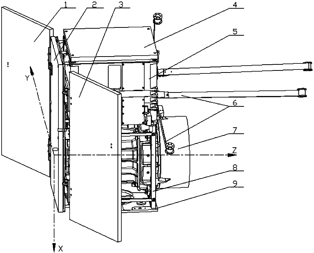
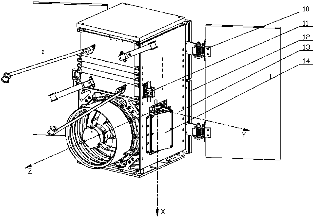
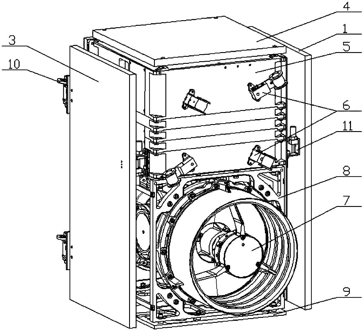
[0049] The present invention is a remote sensing microsatellite, comprising a laminated platform structure 5, a first body-mounted solar sail panel 2, a second body-mounted solar sail panel 4, a first unfolded solar sail panel 1, and a second unfolded solar sail Board 3, load camera 7, load frame 8, bottom plate 9, battery array bracket 12, heat sink 13, electronic cabin heat sink 14, four antennas 6, four hinges 10 and two hot knife brackets 11.

[0050] The load frame 8 is fixed on the bottom of the platform structure 5 by eight screws, and is separated by a polyimide heat-insulating gasket. The load camera 7 is fixed in the load frame 8 by twelve screws, and is separated by a polyimide heat-insulation gasket. separated; the bottom plate 9 is fixed on the bottom of the load frame 8 by eight screws, and is separated by a polyimide heat-insulating gasket; the battery array support 12 is fixed on the -Z side of the platform structure 5 by nine screws, and used Separated by poly...


PUM


Abstract

The invention discloses a remote-sensing microsatellite. The remote-sensing microsatellite comprises a stacked-type platform structure, a first body-mounted solar panel, a second body-mounted solar panel, a first expanded-type solar panel, a second expanded-type solar panel, a load camera, a load frame, a bottom plate, a battery array bracket, a heat sink, an electronic cabin heat sink, four antennas, four hinges and two heat knife brackets. According to the remote-sensing microsatellite, the stacked-type platform structure is adopted, assembling is easy, and structural strength is high; all layers of circuit boxes are mutually independent, and thus electromagnetic interference is reduced; the load frame meets mounting of the effective load camera; the mechanical strength of the whole satellite main structure meets the requirement, a satellite-rocket separating device mounting connector is equipped, the implement space and a connector of a thermal control device are simultaneously considered, and thus reliability and using flexibility are improved; and the problems that currently existing remote-sensing microsatellites cannot meet the capability of bearing the large camera load, the functional integration degree is low, the interchangeability of a satellite platform is not strong enough, the production cost is high, and the production period is long are solved.

Description

technical field [0001] The invention belongs to the technical field of microsatellites, in particular to a remote sensing microsatellite. Background technique [0002] Since the 1980s, with the rapid development of technologies such as microelectronics, micromechanics, precision machining, light materials, and high-efficiency energy, the miniaturization of instruments and equipment required on satellites has been promoted. Shorter, lower cost, smaller and more flexible", the research and development of microsatellites is booming in the world. At present, the United States, Germany, the United Kingdom, Japan and other countries have successfully developed small satellite platforms and constellations. Sweden, Denmark, South Korea, Spain, Israel, Brazil, South Africa and other countries also use the development of small satellites as an entry point to develop their own space capabilities. On November 1, 1961, NASA launched the MS-1 communication satellite weighing 67.5 kilogr...

Claims


Application Information

Patent Timeline
Patent Type & Authority Applications(China)
IPC IPC(8): B64G1/10B64G1/44B64G1/66
CPCB64G1/10B64G1/44B64G1/66
Inventor 张翔胡豪斌梁振华马海宁陆正亮邓寒玉刘幸川刘磊
Owner NANJING UNIV OF SCI & TECH
Why Eureka
Try Eureka