Automatic pipe fitting path distribution conveying mechanism

A technology of automatic branching and conveying mechanism, applied in the direction of conveyors, conveyor objects, transportation and packaging, etc., can solve the problems affecting the branching transmission of pipe fittings, the blocking of pipe fittings, and the inability to meet processing and use, so as to achieve reasonable structural design, Avoid the effect of pipe blockage

Inactive Publication Date: 2018-10-19
海宁市波菲特进出口有限公司
View PDF0 Cites 15 Cited by
  • Summary
  • Abstract
  • Description
  • Claims
  • Application Information

AI Technical Summary

Problems solved by technology

In the existing automatic production line of pipe fittings, according to the different production efficiency of each process, one feeder is required to supply pipe fittings to multiple processing or assembly machines, and the pipe fittings are sent separately to realize the automatic and efficient transmission and processing of pipe fittings. During the split conveying process of the existing pipe fittings, it is difficult to conveniently and smoothly divide the pipe fittings conveyed by one material pipe into two or more pipes for conveying. Poor, it often causes jamming of pipe fittings in the process of branch transmission of pipe fittings, which affects the normal branch transmission of pipe fittings, and the existing pipe fittings are difficult to meet the efficiency requirements of the subsequent production and processing process during the transmission and processing process. Quickly discharge the pipe fittings in the conveying material pipe, so as to avoid the pipe fittings in the material pipe being blocked. If the pipe fittings in the material pipe cannot be discharged quickly, it will not only cause extrusion deformation of the pipe fittings, but also affect the front line due to too many pipe fittings in the material pipe. The normal processing and loading of the process makes it difficult for the previous process to process normally and orderly, which cannot meet the needs of processing and use

Method used


Image

  • Automatic pipe fitting path distribution conveying mechanism
  • Automatic pipe fitting path distribution conveying mechanism
  • Automatic pipe fitting path distribution conveying mechanism

Examples


Embodiment Construction

[0017] In order to further describe the present invention, a specific implementation of an automatic pipe branch transmission mechanism will be further described below in conjunction with the accompanying drawings. The following examples are explanations of the present invention and the present invention is not limited to the following examples.

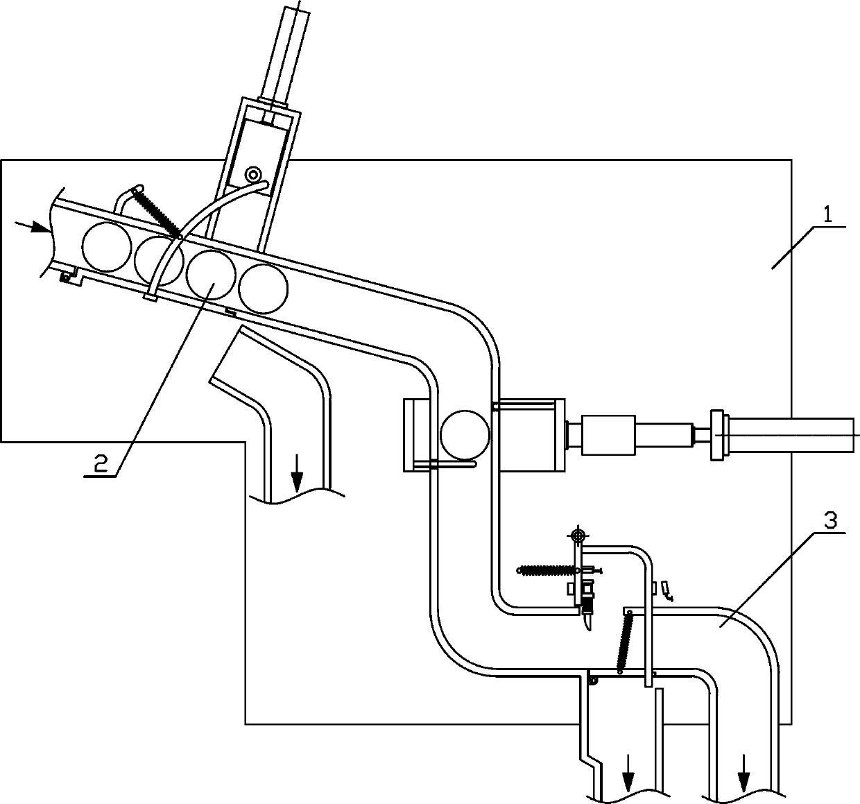
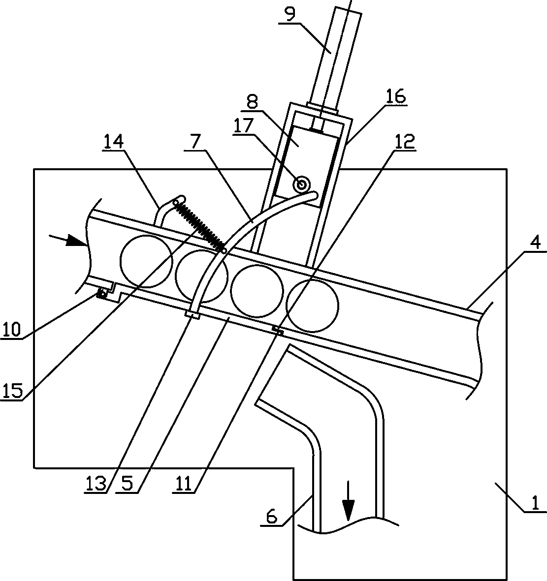
[0018] like figure 1 As shown, an automatic branching transmission mechanism for pipe fittings of the present invention includes a fixed bracket 1, a conduit mechanism 2 and a branching mechanism 3, and the conduit mechanism 2 and the branching mechanism 3 are sequentially arranged on one side of the fixed support 1 from top to bottom. Mechanism 2 and branching mechanism 3 communicate with each other. like figure 2 As shown, the catheter mechanism 2 of the present invention includes a catheter material tube 4, a tube baffle plate 5, a branch material tube 6, a push plate pressing rod 7, a lifting pressure block 8 and a lifting cyli...


PUM


Abstract

The invention discloses an automatic pipe fitting path distribution conveying mechanism, and belongs to the field of workpiece machining conveying mechanical equipment. A guide pipe mechanism and a path distribution mechanism of the automatic pipe fitting path distribution conveying mechanism are sequentially arranged on one side of a fixed bracket from top to bottom; a distribution pipe materialpipe is obliquely arranged in the position, on the lower side of a guide pipe material pipe, of the fixed bracket; the lower side of the guide pipe material pipe is provided with a bearing pipe baffle; the upper end of a material supplying pipe communicates with the lower end of the guide pipe material pipe; a front path distribution material pipe is vertically arranged in the middle of the lowerside of the material supplying pipe, and a rear path distribution material pipe is vertically arranged at the tail end of the lower side of the material supplying pipe; a material separation mechanismis horizontally arranged on the upper side of the material supplying pipe; and the upper end of the front path distribution material pipe is provided with a rotary baffle, and one side of the lower end of a hook rotary plate located on one side of a reciprocating rotary plate is provided with a hook mechanism. The automatic pipe fitting path distribution conveying mechanism is reasonable in structural design, can stably and efficiently distribute pipe fittings into paths for conveying and can discharge the pipe fittings according to the rear path pipe fitting machining load requirement, the automation degree of pipe fitting path distribution conveying is increased, and the production using requirements are met.

Description

technical field [0001] The invention belongs to the field of workpiece processing and conveying machinery, and in particular relates to an automatic branching conveying mechanism for pipe fittings, which is mainly used for continuous conveying and processing of pipe fittings. Background technique [0002] Pipe fittings refer to workpieces with a cylindrical structure. There are many types of pipe fittings. Different pipe fittings use different materials. The quality of the material directly determines the quality of the pipe fittings. Pipe fittings are necessary materials for construction engineering and mechanical equipment. A general term for components that play the roles of connection, control, direction change, flow diversion, sealing, support, etc. Steel pipe fittings are the most important type of pipe fittings. Steel pipe fittings are pressure-bearing pipe fittings. According to different processing techniques, steel pipe fittings can be divided into: butt welding pi...

Claims


Application Information

Patent Timeline
Patent Type & Authority Applications(China)
IPC IPC(8): B65G47/82B65G47/24
CPCB65G47/82B65G47/24B65G2201/0214
Inventor 沈洁
Owner 海宁市波菲特进出口有限公司
Why Eureka
Try Eureka