
Burner with gasification agent and raw coal gas mixed completely and complete mixing and gasification method for gasification agent and raw coal gas

A technology of gasification agent and crude gas, which is used in the gasification of granular/powdered fuel, the manufacture of combustible gas, and the petroleum industry.

Inactive Publication Date: 2018-10-19
HARBIN INST OF TECH
View PDF4 Cites 0 Cited by
  • Summary
  • Abstract
  • Description
  • Claims
  • Application Information

AI Technical Summary

Problems solved by technology

[0008] The present invention aims to solve the problems of slagging at the nozzle of the existing burner and clogging of the lower slag port, and provides a burner and a gasification method for fully mixing gasification agent and crude gas

Method used


Image

  • Burner with gasification agent and raw coal gas mixed completely and complete mixing and gasification method for gasification agent and raw coal gas
  • Burner with gasification agent and raw coal gas mixed completely and complete mixing and gasification method for gasification agent and raw coal gas
  • Burner with gasification agent and raw coal gas mixed completely and complete mixing and gasification method for gasification agent and raw coal gas

Examples


specific Embodiment approach 1

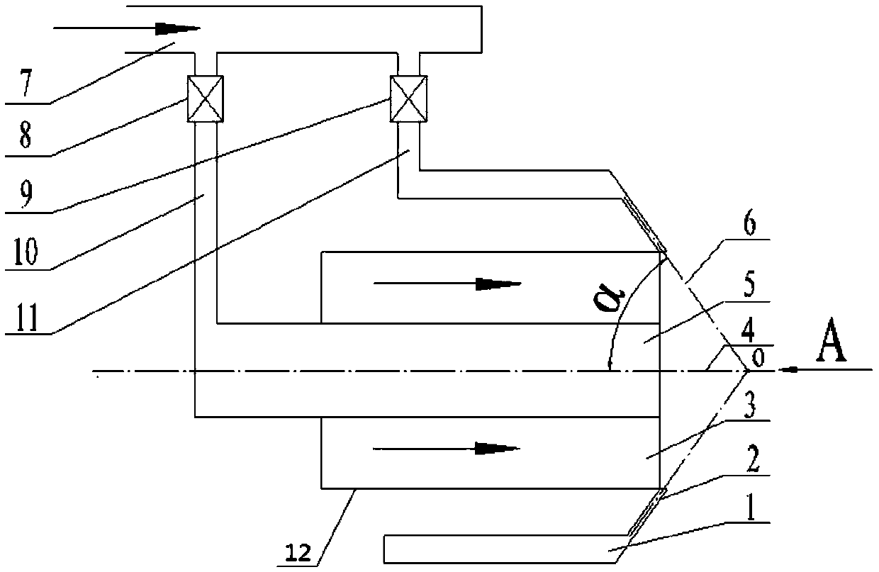
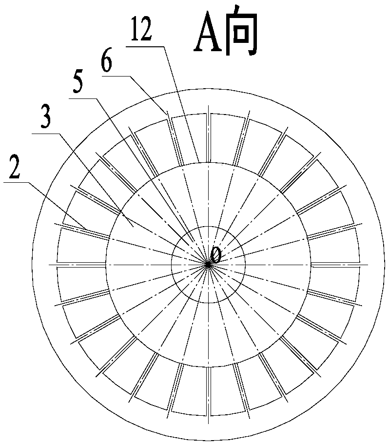
[0037] Specific Embodiment 1: In this embodiment, the gasification agent and crude gas fully mixed burner includes an annular external gasification agent channel (1), an external gasification agent nozzle (2), an annular gasification channel (3), a central gasification agent channel (5), gasification agent main pipe (7), central gasification agent flow regulating valve (8), external gasification agent flow regulating valve (9), central gasification agent delivery pipeline (10) and external gasification Agent delivery pipeline (11);

[0038] Along the radial direction of the burner from inside to outside, the central gasification agent channel (5), the annular gasification channel (3) and the annular outer gasification agent channel (1) are coaxially arranged, and the three channels are parallel to each other;

[0039] The end of the external gasification agent channel (1) close to the gasification chamber of the gasifier is evenly connected with 20 to 60 external gasification ...

specific Embodiment approach 2

[0043] Embodiment 2: This embodiment differs from Embodiment 1 in that: the external gasification agent nozzle (2) is a circular tube, a regular polygonal tube or an irregular polygonal tube. Others are the same as in the first embodiment.

specific Embodiment approach 3

[0044] Embodiment 3: This embodiment differs from Embodiment 1 in that: the diameters of the equal-area circles in the cross-section of the external gasification agent nozzle (2) are the same or different. Others are the same as in the first embodiment.


PUM


Abstract

The invention discloses a burner with a gasification agent and a raw coal gas which are mixed completely and a complete mixing and gasification method for the gasification agent and the raw coal gas,relates to the burner and a gasification method applying the burner, and aims to solve the problems that slag is bonded at an ejection hole of a conventional burner and slag is blocked at a slag discharge hole. The burner comprises an annular external gasification agent channel, an external gasification agent nozzle, an annular gas channel, a central gasification agent channel, a gasification agent main tube, a central gasification agent flow adjusting valve, an external gasification agent flow adjusting valve, a central gasification agent conveying pipeline and an external gasification agentconveying pipeline. The method comprises the following steps: I, aligning the burner to a gasification chamber, and ejecting a raw coal gas into the gasification chamber from the annular coal gas channel; II, dividing the gasification agent into two air flows by the gasification agent main tube; III, ejecting the two flows of the gasification agent into the gasification chamber from the external gasification agent nozzle and the central gasification agent channel. The burner is applied to the field of raw coal gas purification.

Description

technical field [0001] The invention relates to a burner and a gasification method using the burner. Background technique [0002] Fluidized bed, circulating fluidized bed and other low-temperature coal gasification systems with a temperature lower than 1300 °C, the crude gas produced contains fly ash with high combustible content and more organic substances such as tar and phenols. The high content of combustibles in fly ash leads to low effective gas composition and high energy consumption, which reduces the economic benefits of enterprise production. Organic substances such as tar and phenols in the gas will produce a large amount of waste water containing ammonia, phenol and cyanide during the washing process. This type of wastewater contains more organic matter, causing eutrophication of the water body, affecting the survival of aquatic organisms, and even deteriorating the water quality. Phenols and cyanides are highly toxic, and a large amount of discharge will caus...

Claims


Application Information

Patent Timeline
IPC IPC(8): C10J3/48C10J3/50
CPCC10J3/485C10J3/506
Inventor 李争起方能王家全陈智超曾令艳张斌
Owner HARBIN INST OF TECH
Learn More