Hydraulic power unit valve block structure, hydraulic power unit and applied forklift

A technology of hydraulic power unit and valve block, which is applied to engine components, fluid pressure actuating devices, and devices used to relieve pressure on sealing surfaces, etc. The effect of simple and stable adjustment, simple and convenient operation, and simplified structure

Pending Publication Date: 2018-10-19
罗弦
View PDF6 Cites 3 Cited by
  • Summary
  • Abstract
  • Description
  • Claims
  • Application Information

AI Technical Summary

Problems solved by technology

[0007] An object of the present invention is to overcome the shortcomings of the existing hydraulic power unit valve block structure such as complex structure and cumbersome hydraulic flow adjustment operation, and provide a hydraulic power unit valve block structure and hydraulic power unit. Using the technical solution of the present invention, by rotating The telescopic movement of the ejector rod controls the linkage of two groups of valve cores in the valve block, which cleverly realizes the gradual adjustment of the oil supply flow rate, the flow adjustment is simple and stable, and the oil return action can be controlled by the ejector rod rotation, without the need to install additional valves on the valve block. All kinds of electromagnetic control valves simplify the structure of the valve block and make the operation more simple and convenient; at the same time, there is a pressure relief valve in the valve block to ensure the safety and stability of the oil supply pressure of the equipment, which has very good promotion and application value

Method used


Image

  • Hydraulic power unit valve block structure, hydraulic power unit and applied forklift
  • Hydraulic power unit valve block structure, hydraulic power unit and applied forklift
  • Hydraulic power unit valve block structure, hydraulic power unit and applied forklift

Examples


Embodiment 1

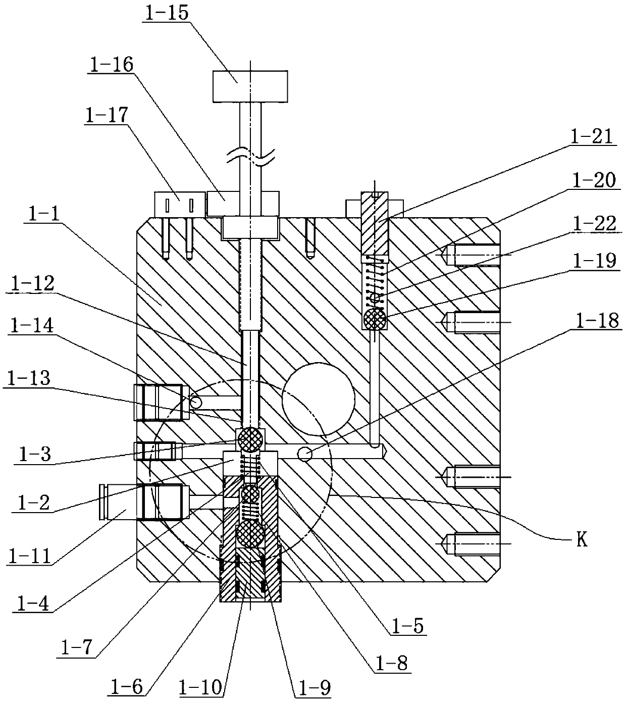
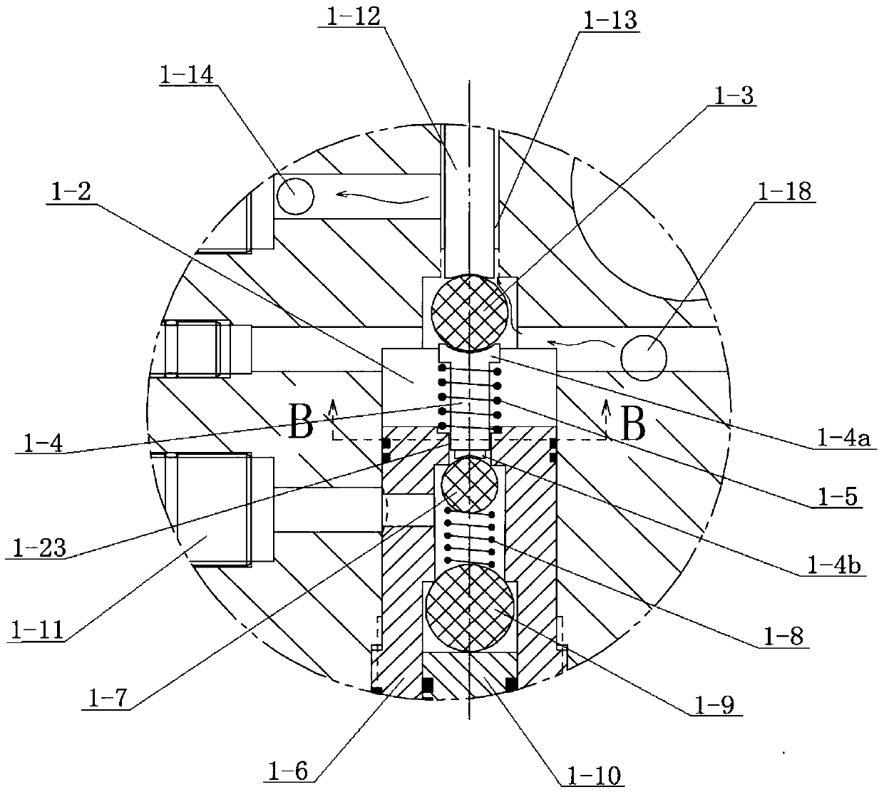
[0040] to combine Figure 2 to Figure 5 As shown, a valve block structure of a hydraulic power unit in this embodiment includes a valve body 1-1, and a first valve core hole 1-2, an oil inlet hole 1-18, and a return valve arranged in the valve body 1-1. The oil hole 1-14, the oil outlet hole and the adjustment mechanism located in the first spool hole 1-2, the adjustment mechanism includes the first adjustment spool, the first spool elastic member 1-5, the spool cover 1- 6. The second regulating spool 1-7, the second spool elastic member 1-8 and the ejector rod 1-12, the oil inlet hole 1-18 communicates with the first valve core hole 1-2, and the ejector rod 1-12 It is installed in the ejector rod hole of the valve body 1-1, and can move telescopically in the ejector rod hole through rotation. Specifically, threaded connection can be used to convert the rotation action of the ejector rod 1-12 into telescopic movement. The ejector rod hole and the first The spool hole 1-2 comm...

Embodiment 2

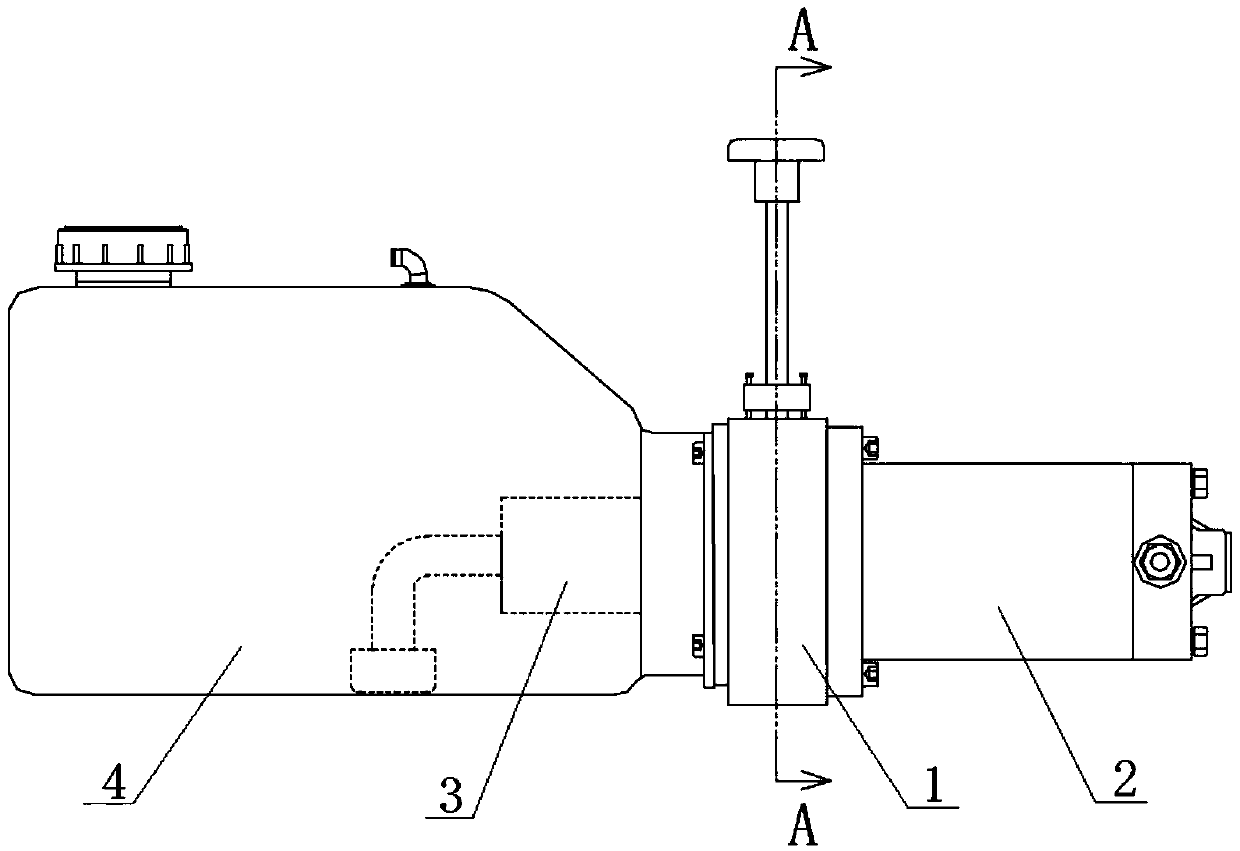
[0044] to combine figure 1 As shown, a hydraulic power unit of this embodiment includes a valve block 1, a motor 2, a gear pump 3 and an oil tank 4, and the valve block 1 adopts the valve block structure of the hydraulic power unit in Embodiment 1, and the valve block 1 is installed on Between the motor 2 and the gear pump 3, the output shaft of the motor 2 passes through the valve block 1 and is connected to the gear pump 3, the fuel tank 4 is connected to the gear pump 3, and the oil inlet holes 1-18 in the valve block 1 are connected to the gear pump 3 The oil inlet is connected, the oil return hole 1-14 and the oil drain hole 1-22 are connected with the oil tank 4, and the oil outlet hole is connected with the oil pipe joint 1-11 on the valve block 1 for connecting with the hydraulic equipment. A joystick 1-15 is provided on the valve block 1, and the ejector rod 1-12 is connected with the joystick 1-15; the joystick 1-15 has at least an oil supply flow adjustment control ...

Embodiment 3

[0047] This embodiment discloses a forklift using the hydraulic power unit described in Embodiment 2 above. The hydraulic power unit described in Example 2 is used in a forklift to replace the existing hydraulic power unit. According to practical use, the forklift lifts slowly at the beginning, and then the speed gradually increases, and the lift is stable and reliable. -15 can be controlled more flexibly, the forklift lifting action is smoother, and the operation is simpler and safer.

[0048] A hydraulic power unit valve block structure of the present invention and the hydraulic power unit and the forklift applied thereto control the linkage of the two groups of valve cores in the valve block through the rotating and telescopic movement of the ejector rod, and skillfully realize the gradual adjustment of the oil supply flow rate. The adjustment is simple and stable, and the oil return action can be controlled by the rotation of the ejector rod. There is no need to install va...


PUM


Abstract

The invention discloses a hydraulic power unit valve block structure, a hydraulic power unit and an applied forklift, and belongs to the technical field of hydraulic oil supply. According to the hydraulic power unit valve block and the hydraulic power unit, an ejector rod which rotatably and telescopically moves controls two sets of valve elements in a valve block to be linked, gradual changing ofoil supply flow can be ingeniously achieved, flow adjusting is simple and stable, the ejector rod rotates to control the oil returning action, various kinds of electromagnetic control valves do not need to be additionally arranged on the valve block, the structure of the valve block is simplified, operation is simpler and more convenient, a pressure relief valve is arranged in the valve block, equipment oil supply pressure safety and stability are ensured, and the good application and popularization value is achieved; according to the forklift with the hydraulic power unit, the hydraulic power unit is used on the forklift, the forklift more smoothly ascends and descends, and operation is more easy and safe.

Description

technical field [0001] The invention relates to a hydraulic oil supply device, more specifically, to a valve block structure of a hydraulic power unit, a hydraulic power unit and an applied forklift. Background technique [0002] In the machinery industry, because of the advantages of hydraulic transmission such as light weight, small size, small motion inertia, and fast response, many products need to be powered by hydraulic technology. The hydraulic power unit is the heart of the hydraulic system, which provides power for the hydraulic system. As the oil supply device in the hydraulic system, the hydraulic power unit is widely used in mechanical equipment such as lifting mechanisms, dump vehicles, working platforms, presses, machine tools, etc. Compared with conventional hydraulic stations, it has small size and light weight , energy saving and reliable, cheap and other advantages. [0003] The existing hydraulic power unit is generally assembled by a motor, a valve bloc...

Claims


Application Information

Patent Timeline
IPC IPC(8): F15B13/02F16K11/14F16K39/02B66F9/22
CPCF15B13/02F16K11/14F16K39/024B66F9/22
Inventor 罗弦罗青海
Owner 罗弦
Why Eureka
Try Eureka