Intelligent industrial furnace and use method

An industrial furnace, intelligent technology, applied in furnaces, furnace components, furnace control devices, etc., can solve the problems of environmental pollution, waste gas without purification function, low degree of intelligent automation, etc., to protect the environment, reduce emissions, and ensure quality Effect

Inactive Publication Date: 2018-10-19
天津赫鑫机械设备有限公司
0 Cites 0 Cited by

AI-Extracted Technical Summary

Problems solved by technology

[0002] Industrial furnaces are thermal equipment that use heat from fuel combustion or electrical energy conversion to heat materials or workpieces in industrial production. Most of the traditional industrial furnaces use high-efficiency fuels and cannot use inferior fuels for combustion. However, fuel supply is currently tight. , in the face of the energy crisis, it is necessary to solve the energy crisis and improve the energy utilization rate. In addition, the exhaust gas produced by the existing industrial furnaces has no purification function, and the exhaust gas produced is directly discharged into the atmosphere, which brings certain pollution to the environm...

Abstract

The invention discloses an intelligent industrial furnace and a use method. The intelligent industrial furnace comprises a feeding port, a preheating furnace and a heating furnace, wherein the feedingport is formed in the upper part of the preheating furnace; the heating furnace is arranged at one side of the preheating furnace, and a pressure regulator is arranged at the upper part of the heating furnace; an exhausting pipe is arranged to one side of the pressure regulator, and a gas detector is arranged in the exhausting pipe; a carbon fiber filter is arranged at the lower part of the gas detector; a gas reaction absorber is arranged at the lower part of the carbon fiber filter; an activated carbon absorbing layer is arranged at the lower part of the gas reaction absorber; a primary filter is arranged at the lower part of the activated carbon absorbing layer; a pressure sensor is arranged in the preheating furnace; and a temperature sensor is arranged at one side of the pressure sensor. The intelligent industrial furnace has the beneficial effects that the industrial furnace can be intelligently adjusted and controlled to run, and meanwhile, exhausted harmful gas is reduced, sothat the environment is protected; the pressure and the temperature in the furnace can be effectively accurately controlled, and thus the produced product quality is ensured.

Application Domain

Preheating chargesControl devices for furnaces +2

Technology Topic

Activated carbonProcess engineering +6

Image

  • Intelligent industrial furnace and use method
  • Intelligent industrial furnace and use method
  • Intelligent industrial furnace and use method

Examples

  • Experimental program(1)

Example Embodiment

[0024] The present invention will be further explained below in conjunction with the drawings:
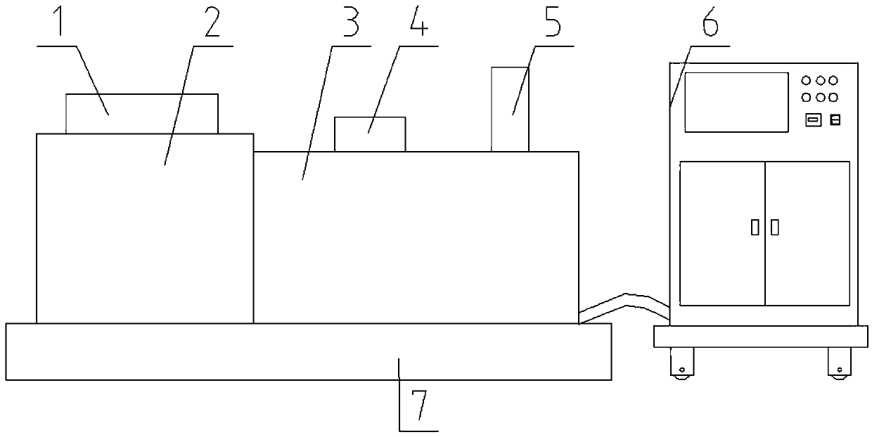
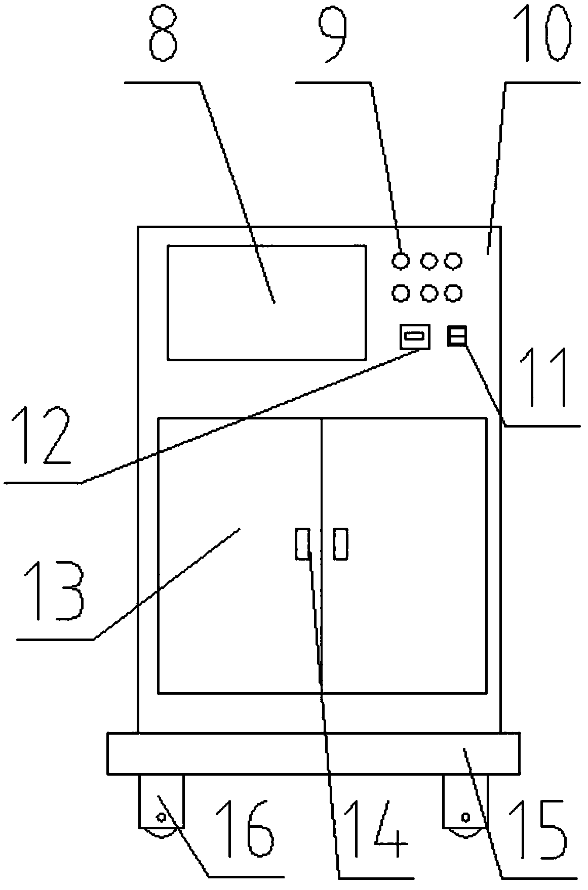
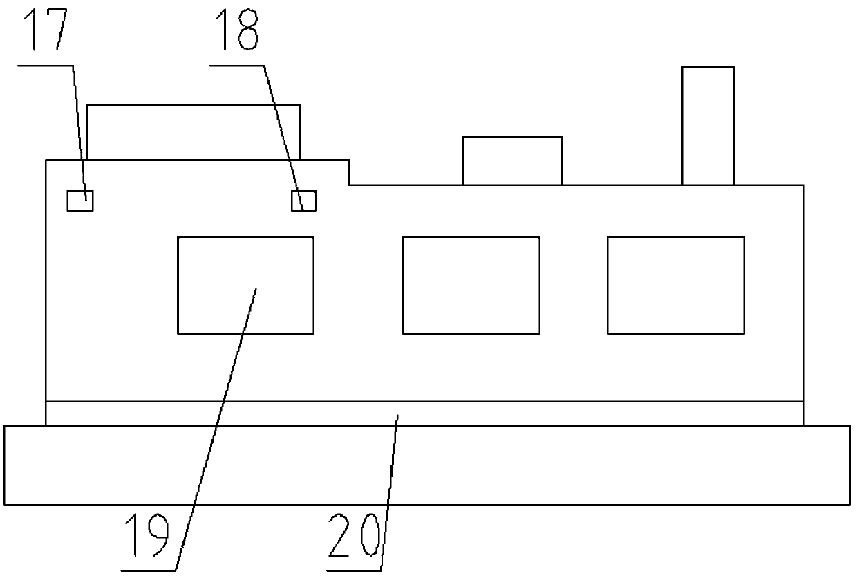
[0025] Such as Figure 1-Figure 4 As shown, an intelligent industrial furnace includes a feed port 1, a preheating furnace 2, and a heating furnace 3. The feed port 1 is provided above the preheating furnace 2, and one side of the preheating furnace 2 is provided There is the heating furnace 3, a pressure regulator 4 is arranged above the heating furnace 3, an exhaust pipe 5 is arranged on one side of the pressure regulator 4, and a gas detector 21 is arranged in the exhaust pipe 5, so A carbon fiber filter 22 is arranged below the gas detector 21, a gas reaction absorber 23 is arranged below the carbon fiber filter 22, and an activated carbon absorption layer 24 is arranged below the gas reaction absorber 23. Below the activated carbon absorption layer 24 A preliminary filter 25 is provided, a pressure sensor 17 is provided in the preheating furnace 2, a temperature sensor 18 is provided on one side of the pressure sensor 17, and a heating couple 19 is provided under the temperature sensor 18, and the heating power A heating plate 20 is arranged under the couple 19, a base 7 is arranged under the heating furnace 3, and a smart electric control cabinet 6 is arranged on one side of the base 7, and a casing 10 is arranged outside the intelligent electric control cabinet 6. A display screen 8 is provided on the surface of the housing 10, a control button 9 is provided on one side of the display screen 8, a smart temperature controller 12 is provided below the control button 9, and a power switch is provided on one side of the smart temperature controller 12 11. A cabinet door 13 is provided under the display screen 8, a handle 14 is provided on the surface of the cabinet door 13, a support base 15 is provided under the cabinet door 13, and a moving wheel 16 is provided under the support base 15.
[0026] In this embodiment, the preheating furnace 2 is welded to the base 7, the heating furnace 3 is welded to the base 7, and the feed inlet 1 is welded to the preheating furnace 2.
[0027] In this embodiment, the voltage regulator 4 and the heating furnace 3 are connected by screws, the exhaust pipe 5 is connected with the heating furnace 3 by threads, and the heating furnace 3 is connected to the intelligent electric control cabinet 6 Connect by wire.
[0028] In this embodiment, the pressure sensor 17 is connected to the preheating furnace 2 by screws, the temperature sensor 18 is connected to the heating furnace 3 by screws, and the heating couple 19 and the heating furnace 3 are connected by screws. Connection, there are three heating couples 19, the model of the pressure sensor 17 is MS5611-01BA, and the model of the temperature sensor 18 is WRM-101.
[0029] In this embodiment, the heating plate 20 and the base 7 are connected by bolts, the casing 10 and the display screen 8 are connected by screws, and the control button 9 is nested and connected with the casing 10.
[0030] In this embodiment, the smart temperature controller 12 is connected with the housing 10 by screws, the power switch 11 is nested and connected with the housing 10, and the cabinet door 13 and the housing 10 are connected by a hinge. connection.
[0031] In this embodiment, the housing 10 and the support base 15 are welded, the cabinet door 13 and the handle 14 are connected by screws, and the support base 15 and the moving wheel 16 are connected by a pin.
[0032] In this embodiment, the gas detector 21 is connected to the exhaust pipe 5 by screws, the carbon fiber filter 22 is nested and connected to the exhaust pipe 5, and the gas reaction absorber 23 is connected to the exhaust pipe 5. The air pipe 5 is nested and connected, the activated carbon absorption layer 24 is nested and connected to the exhaust pipe 5, and the preliminary filter 25 is nested and connected to the exhaust pipe 5.
[0033] In this embodiment, the temperature sensor 18 is connected to the smart electric control cabinet 6 through a wire, the pressure sensor 17 is connected to the smart electric control cabinet 6 through a wire, and the heating couple 19 is connected to the smart electric The control cabinet 6 is connected by wires, and the gas detector 21 and the intelligent electric control cabinet 6 are connected by wires.
[0034] The present invention also provides a method for using an intelligent industrial furnace, which is applied to the above-mentioned intelligent industrial furnace. The specific method of use is: inputting control commands through the control button 9 to set the heating temperature, time and furnace body The material is put into the preheating furnace 2 from the feed port 1, the heating couple 19 cooperates with the heating plate 20 to preheat the material, and then the material is preheated in the heating furnace 3. For heat treatment, the voltage regulator 4 can adjust the pressure in the furnace. The pressure sensor 17 monitors the pressure and changes in the furnace. When the value exceeds or falls below the rated value, the intelligent electric control cabinet 6 receives the signal. The operator will be reminded to automatically control the pressure regulator 4 to adjust the pressure in the furnace. The temperature sensor 18 monitors the temperature in the furnace. During normal operation, the intelligent temperature controller 12 controls the temperature in the furnace. Stable. When the temperature is abnormal, the intelligent electric control cabinet 6 will alarm and automatically adjust the temperature. Some waste gas will be generated during the heating of the material. The preliminary filter 25 performs preliminary filtering of the gas, and the activated carbon absorption layer 24 absorbs For small particles in the gas, the gas reaction absorber 23 is used to absorb some harmful substances in the reaction gas, the carbon fiber filter 22 is used for final filtration, and the gas detector 21 detects that the gas quality reaches the standard, the The intelligent electric control cabinet 6 will control the gas emission. When the gas does not meet the standard, the intelligent electric control cabinet 6 will remind the staff.
[0035] The above shows and describes the basic principles, main features and advantages of the present invention. Those skilled in the industry should understand that the present invention is not limited by the foregoing embodiments. The foregoing embodiments and descriptions only illustrate the principles of the present invention. Without departing from the spirit and scope of the present invention, the present invention will have Various changes and improvements, these changes and improvements all fall within the scope of the claimed invention.

PUM

no PUM

Description & Claims & Application Information

We can also present the details of the Description, Claims and Application information to help users get a comprehensive understanding of the technical details of the patent, such as background art, summary of invention, brief description of drawings, description of embodiments, and other original content. On the other hand, users can also determine the specific scope of protection of the technology through the list of claims; as well as understand the changes in the life cycle of the technology with the presentation of the patent timeline. Login to view more.

Similar technology patents

Economic development zone comprehensive energy system planning method based on minimum annual comprehensive cost

PendingCN110197300Aemission reductionReduce environmental protection costs
Owner:WENZHOU ELECTRIC POWER BUREAU +1

Recycling method for phthalic anhydride residues

Owner:辽宁东野环保产业开发有限公司

Environmentally-friendly diesel engine oil with long oil drain intervals, and preparation method thereof

InactiveCN110452763AGood synergistic effectemission reduction
Owner:CHAMBROAD CHEM IND RES INST CO LTD

Classification and recommendation of technical efficacy words

  • emission reduction
  • protect environment
Why Eureka
Try Eureka