Multi-scale microstructure reactor

A microstructure reactor, multi-scale technology, applied in chemical/physical/physical chemical reactors, chemical instruments and methods, chemical/physical/physical chemical processes, etc., can solve the problem of long mixing time, complex structure, and reduced mass transfer Heat transfer rate and other issues, to achieve good mixing state, fast mass transfer rate, high mixing effect

Active Publication Date: 2018-10-23
SHANGHAI JIAO TONG UNIV
View PDF5 Cites 1 Cited by
  • Summary
  • Abstract
  • Description
  • Claims
  • Application Information

AI Technical Summary

Problems solved by technology

[0004] The present invention aims at the complex structure and long mixing time of the prior art, and for the multiphase reaction system, the pipeline area between the cylinder body and the multi-layer spiral wound microchannel reactor is prone to condensation of droplets and bubbles and even fluid separation. layer phenomenon, which greatly reduces the mass transfer and heat transfer rate and other defects. A multi-scale microstructure reactor is proposed. Rapid and efficient mixing and reaction under low volume, and the internal structure is simple, easy to process and manufacture

Method used


Image

  • Multi-scale microstructure reactor
  • Multi-scale microstructure reactor

Examples


Embodiment 1

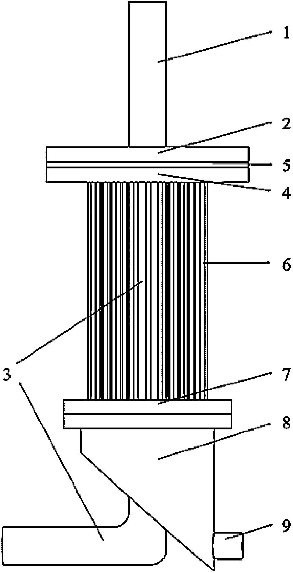
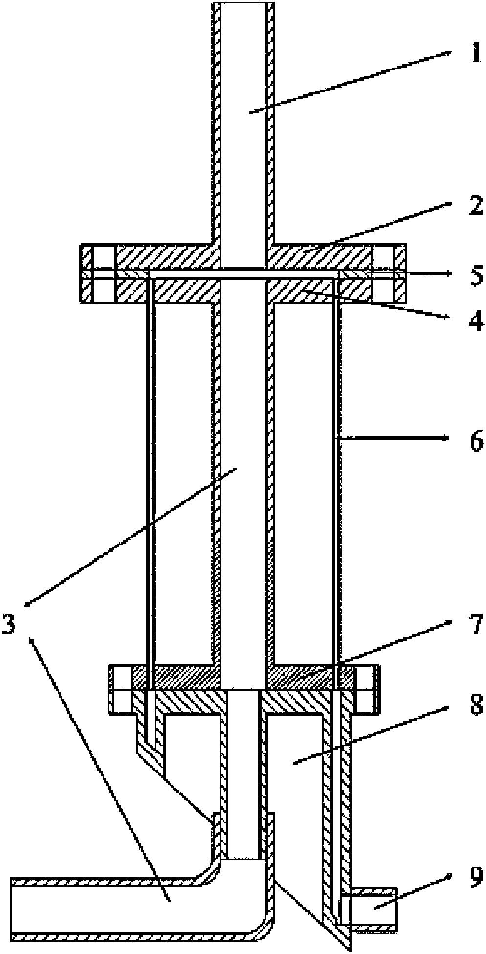
[0022] Such as figure 1 As shown, this embodiment includes: a lower fluid inlet pipe 3, a lower fluid inlet flange 4, an upper fluid inlet pipe 1, an upper fluid inlet flange 2, a mixing chamber 5, a capillary tube 6, and a collection chamber connected sequentially from top to bottom The cover plate 7, the collection chamber 8 and the outlet pipe 9, wherein: the upper fluid inlet pipe 1 and the lower fluid inlet pipe 3 are arranged coaxially, and pass through the upper fluid inlet flange 2 and the lower fluid inlet respectively from above and below the mixing chamber 5 The flange 4 communicates with the mixing chamber 5; the capillary 6 is arranged radially around the lower fluid inlet pipe 3 in a single-layer or multi-layer annular array, and clings to the inner wall of the mixing chamber 5.

[0023] The mixing chamber 5 is an annular thin flange.

[0024] The thickness of the mixing chamber 5 is 0.5-5mm, and the inner diameter is 10-500mm.

[0025] The mixing chamber 5 can...

Embodiment 2

[0042] The diameter of the upper fluid inlet pipe 1 and the lower fluid inlet pipe 3 are both 3mm, the thickness of the mixing chamber 5 is 1mm, and there are 630 capillaries with an inner diameter of 0.75mm and a length of 0.1m.

[0043] In this example, chemical probe technology was used to characterize the mixing performance of the reaction system.

[0044] Described reaction system is: H 2 BO 3 - +H + →H 3 BO 3 , 5I - +IO 3 - +6H + →3I 2 +3H 2 O;

[0045] The generated iodine will be further combined with I - Reaction I 3 - :

[0046] Detection of I by UV absorption spectroscopy 3 - concentration, and then calculate the separation index: where: X s is the separator index, C i is the concentration of component i substance, unit mol / L; V is the concentration of H 2 BO 3 - , I - and IO 3 - The volume flow rate of the solution, in mL / min; n i is the amount of component i substance, unit mol; subscript O indicates the value in the initial state.

[...


PUM

PropertyMeasurementUnit
Thicknessaaaaaaaaaa
The inside diameter ofaaaaaaaaaa

Abstract

A multi-scale microstructure reactor comprises: a lower fluid inlet tube; and an upper fluid inlet tube, a mixing chamber, capillary tubes, a collection chamber cover plate, a collection chamber and an outlet tube which are sequentially communicated from top to bottom, wherein the upper fluid inlet tube and the lower fluid inlet tube are coaxially arranged, and are respectively communicated with the mixing chamber from the top and the bottom of the mixing chamber; and the capillary tubes are radially arranged around the lower fluid inlet tube in an annular array, and cling to the inner wall ofthe mixing chamber. The multi-scale microstructure reactor has the advantages of flexibility in operation, good mixing effect, realization of large-scale production of chemical products through adjusting the quantity and the size of the capillary tubes, and great application potential in the fields of chemistry, chemical engineering, petrochemicals and medicines.

Description

technical field [0001] The invention relates to a technology in the field of chemical rapid mixing and reaction equipment, in particular to a multi-scale microstructure reactor. Background technique [0002] In many fields such as chemistry, chemical industry, petrochemical and pharmaceutical, especially the reaction and separation (such as gas absorption and liquid-liquid extraction) process of chemical industry, it is necessary to carry out the mixing and reaction between two or more strands of materials. The quality of the reaction process has a crucial relationship with the smooth progress of the reaction process and the overall process efficiency. Traditional mixing and reaction equipment, such as fully mixed tanks and tower reactors, have a large processing capacity and can meet the requirements of large-scale industrial production. However, because the mixing scale or reaction scale in the equipment is at the millimeter or even larger The efficiency is low, the resid...

Claims


Application Information

Patent Timeline
IPC IPC(8): B01J19/00
CPCB01J19/0093
Inventor 苏远海李光晓商敏静
Owner SHANGHAI JIAO TONG UNIV
Why Eureka
Try Eureka