Microfluid analysis box

A microfluidic and microfluidic structure technology, applied in the field of microfluidics, can solve the problems of extremely high processing precision, high hydrophilic treatment requirements, reduced product reliability, portability, etc.

Pending Publication Date: 2018-10-23
NINGBO AUCHEER BIOTECHNOLOGY CO LTD
View PDF2 Cites 8 Cited by
  • Summary
  • Abstract
  • Description
  • Claims
  • Application Information

AI Technical Summary

Problems solved by technology

However, US20100009430A1 requires the paths of the upper and lower surfaces to be completely aligned, which requires extremely high processing precision of the product. At the same time, since the drainage channel has no side walls, the requirements for the hydrophilic treatment of the surface of the structure are also extremely high.
The technical solution disclosed in CN104204800A requires an external air pressure control device, which adds additional control components and reduces the reliability and portability of the product

Method used


Image

  • Microfluid analysis box
  • Microfluid analysis box
  • Microfluid analysis box

Examples


Embodiment 1

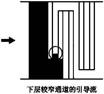
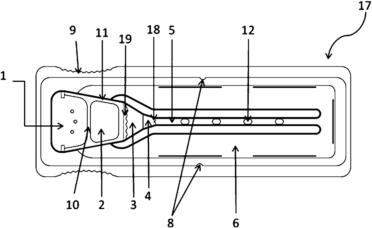
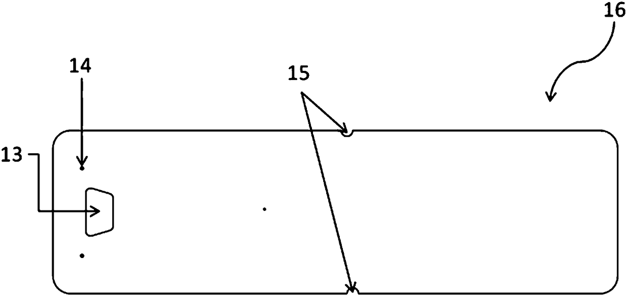
[0064] to attach Figure 5 The analysis box shown is an example, the operator can hold the structure 9 that is easy to grasp by hand and from the sample injection hole 13 of its upper cover 16 (see the attached figure 2 ) add the liquid sample containing the analyte to the sample receiving area 1 of the base 17 (see attached figure 1 ), the liquid sample flows into the sample storage area 2 through the isolation rod 10, then flows into the incubation area 3 through a wave-shaped structure 19, and enters the time valve 4 after combining with the detection reagent fixed on the microcolumn in the incubation area 3. The time valve is a staggered stagnation bar structure (see accompanying drawing 3), and the side view of each stagnation bar is stepped (referring to the accompanying drawing Figure 3B -a), the liquid containing the sample-detection reagent combination flows through the drainage structure 18 at a uniform speed in the diversion groove to the detection channel 5 and ...

Embodiment 2

[0066] to attach Figure 5 The analysis box shown is an example, the operator can hold the structure 9 that is easy to grasp by hand and from the sample injection hole 13 of its upper cover 16 (see the attached figure 2 ) add the liquid sample containing the analyte to the sample receiving area 1 of the base 17 (see attached figure 1 ), the liquid sample flows into the sample storage area 2 through the isolation rod 10, then flows into the incubation area 3 through a wave-shaped structure 19, and enters the time valve 4 after combining with the detection reagent fixed on the microcolumn in the incubation area 3. This time valve is a block bar structure (see accompanying drawing 3), and the side view of each block bar is trapezoidal (see accompanying drawing 3). Figure 3B -C), the distance between each blocking column is that the liquid containing the sample-detection reagent combination flows through the drainage structure 18 at a uniform speed in the diversion groove to th...

Embodiment 3

[0068] The microfluidic real-time detection chip is formed by bonding an upper cover 16 and a base 17 . The capillary channel has a width of 2 mm and a depth of 200 μm. Wherein the base 17 includes an incoming sample receiving area 1, an isolation rod 10, a sample storage area 2, a wave-shaped structure 19, an incubation area 3, a time valve 4, a drainage structure 18, a detection channel 5 and two detection sites 12 therein, and Waste area 6. The fluid sample is added dropwise from the left sampling port 13, and after being filtered through the filter membrane of the upper cover 16 and base 17 in the sample loading area, the serum in the sample storage area 2 is drained by the wave-shaped structure 19 and quickly enters the incubation area 3. The substance to be detected in the filtered fluid sample is evenly mixed with the reagent in the incubation zone 3, and then enters the body time valve 4. The time valve 4 has the characteristics of reducing the sample flow rate and c...


PUM


Abstract

The invention discloses a microfluid analysis box. The microfluid analysis box comprises a top cover, a pedestal and a microfluid structural zone positioned at the pedestal; the microfluid structuralzone contains a sample reception area, a sample storage zone, an incubation zone, a time valve, a detection channel, and a waste liquid zone; the time valve is a diversion groove formed by retardancebar structures which are staggered bilaterally, and a side view of each retardance bar presents a shape with a wide bottom and a narrow top.

Description

technical field [0001] The invention relates to the field of microfluidics, in particular to a microfluidic rapid diagnosis system. Background technique [0002] Microfluidics refers to the science and technology involved in the use of micropipes (tens to hundreds of microns in size) to process or manipulate tiny fluids (nanoliters to attic liters in volume). Emerging interdisciplinary disciplines of fluid physics, microelectronics, new materials, biology, and biomedical engineering. In the prior art, there is a serpentine drainage channel formed by the corresponding protruding parts of the upper and lower surfaces of the device, and the effect of drainage and flow rate control is achieved by controlling the contact angle between the fluid and the upper and lower surfaces of the channel; Adjust the air pressure at the place to control the flow rate; there are microstructure areas of different shapes on the fluid flow path, and through complex microstructures and further sur...

Claims


Application Information

Patent Timeline
Patent Type & Authority Applications(China)
IPC IPC(8): B01L3/00
CPCB01L3/502746B01L2200/0636B01L2400/0406B01L2400/086
Inventor 蒋理国周鸿章周义正
Owner NINGBO AUCHEER BIOTECHNOLOGY CO LTD
Why Eureka
Try Eureka