An isolated photovoltaic charging device and method

A charging device and isolated technology, applied in circuit devices, battery circuit devices, current collectors, etc., can solve the problems of reliable operation of charging devices, safety hazards, component damage, common mode interference, etc., to improve anti-interference ability and triggering. reliability, prevent damage to components, and solve the effect of common mode interference

Active Publication Date: 2020-08-04
武汉天富海科技发展有限公司
View PDF1 Cites 0 Cited by
  • Summary
  • Abstract
  • Description
  • Claims
  • Application Information

AI Technical Summary

Problems solved by technology

[0003] At present, for photovoltaic charging devices with high voltage (hundreds of volts or even greater) or high current (tens of amps or greater), due to the direct electrical connection between the battery and the photovoltaic panel, there is an electrical connection between the photovoltaic panel and ground. Parasitic capacitance will form a common-mode resonance circuit composed of parasitic capacitance, filter elements and battery charging circuit impedance, thereby forming a common-mode current, which will bring safety hazards to the reliable operation of the charging device. Therefore, a high-frequency transformer is required for isolation , with the help of the built H-bridge inverter circuit to achieve power output
[0004] However, practice shows that in the process of using photovoltaic panels to charge batteries, on the one hand, it is necessary to improve the utilization rate of photovoltaic panels, that is, to allow batteries to store as much energy as possible converted by photovoltaic panels; The discharge rule cannot be charged with a large current for a long time, such as a photovoltaic charging scheme disclosed in the patent document CN106329626A, which includes a power supply module, a main circuit module, a control circuit module, a PWM drive circuit The battery is charged in three stages, and the over-discharged battery is also pre-charged at the same time. However, the main circuit does not adopt a safe isolation method, and there is no real-time monitoring and collection of H-bridge inverter module temperature t, input voltage Vin, input Acquisition data of current Iin, output voltage Vout, output current Iout
In the existing photovoltaic charging device, although the acquisition circuit has optocoupler isolation, since the main circuit does not adopt the isolation method, there may still be common-mode interference, and a high-frequency trigger transformer is required for secondary isolation to ensure that the PWM signal It has a high anti-interference ability, which further improves the reliability of the trigger circuit; at the same time, during the startup process of the circuit, the components of the circuit may be damaged due to excessive startup current, which requires special design at the input end to ensure The entire device is soft-started; in addition, some charging devices will use power frequency transformers for isolation, and as the capacity of the device increases, the size of the entire device will be too large

Method used


Image

  • An isolated photovoltaic charging device and method
  • An isolated photovoltaic charging device and method
  • An isolated photovoltaic charging device and method

Examples


Embodiment Construction

[0038] In order to make the object, technical solution and advantages of the present invention clearer, the present invention will be further described in detail below in conjunction with the accompanying drawings and embodiments. It should be understood that the specific embodiments described here are only used to explain the present invention, not to limit the present invention.

[0039] In addition, the technical features involved in the various embodiments of the present invention described below can be combined with each other as long as they do not constitute a conflict with each other. The present invention will be further described in detail below in combination with specific embodiments.

[0040] For the convenience of introducing the content of the invention, the definitions and explanations of related terms are as follows:

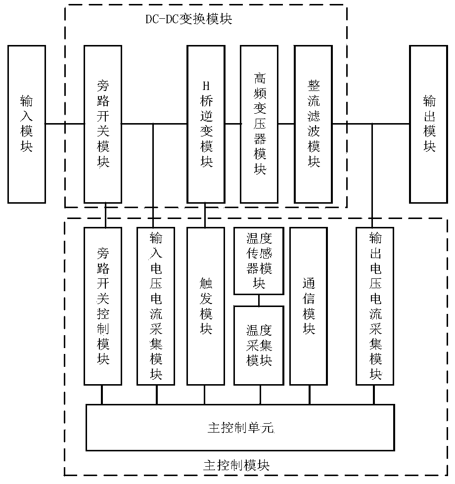
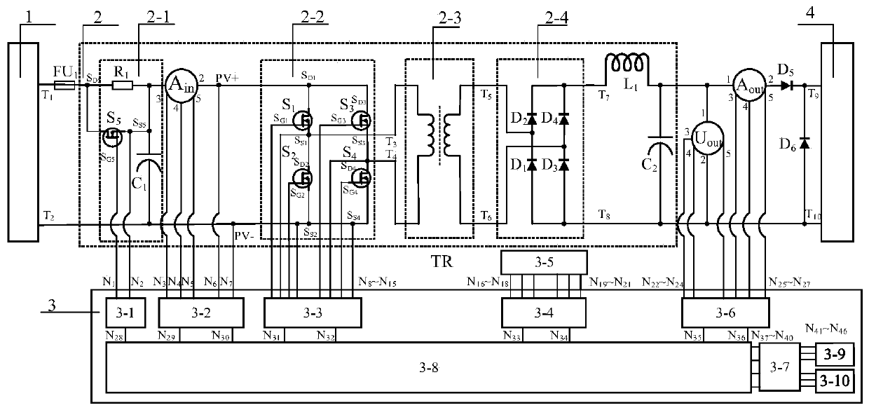
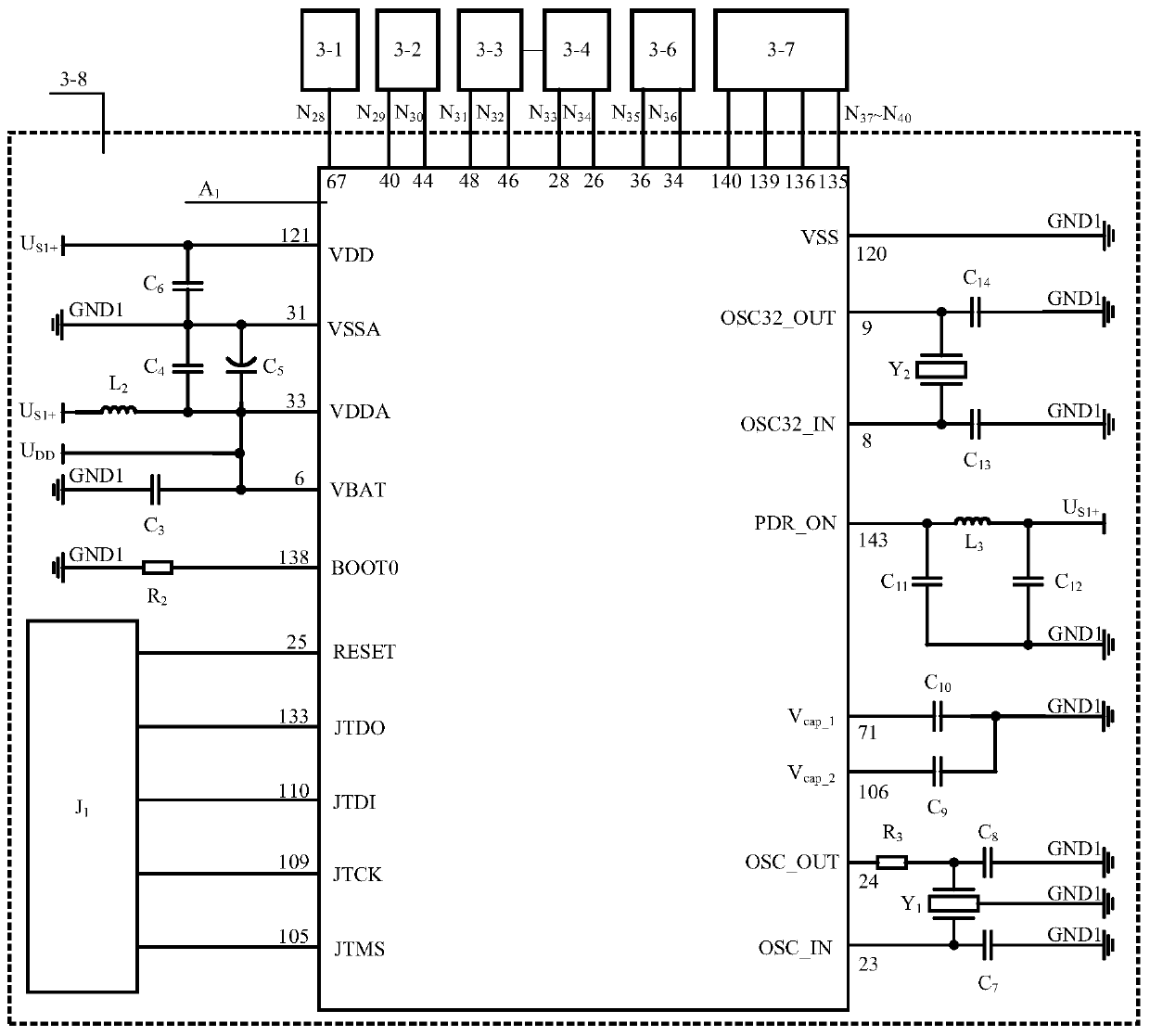
[0041] figure 1 with figure 2 They are a block diagram and a schematic circuit diagram of an isolated photovoltaic charging device accordin...


PUM


Abstract

The invention discloses an isolated photovoltaic charging device comprising an input module, a DC-DC conversion module, a main control module and an output module. The DC-DC conversion module consistsof a bypass switch module, an H-bridge inverter module, a high-frequency transformer module, and a rectifier filter module. The main control module includes a main control unit, an input voltage andcurrent acquisition module, a trigger module, a temperature acquisition module and an output voltage and current acquisition module; the main control unit is used for comparing data, collected in realtime, of an H-bridge inverter module temperature t, an input voltage Vin, an input current Iin, an output voltage Vout, and an output current Iout with standard values of a main control unit databaseand generating a corresponding control instruction based on a comparison result of a current output power and a preset maximum output power so as to drive the trigger module to control connection anddisconnection time of the MOS tube of the H-bridge inverter module and realize sub-stage photovoltaic charging of the direct-current load. With the isolated photovoltaic charging device and method, the utilization rate of photovoltaic charging is increased and the high safety of the direct-current load and the device is guaranteed.

Description

technical field [0001] The invention belongs to the field of power electronics, and in particular relates to an isolated photovoltaic charging device and method. Background technique [0002] Photovoltaic power generation is a technology that uses the photovoltaic effect at the semiconductor interface to directly convert light energy into electrical energy. Photovoltaic power generation uses solar panels to convert the sun's radiant energy into electrical energy, and then sends the electrical energy to the battery for storage or drives a DC load to work. The current solar charging system is mainly composed of solar cells (also known as photovoltaic panels), DC-DC conversion circuits, batteries and control circuits. For low-power photovoltaic charging devices with tens of watts, BUCK circuits are mostly used to manage lithium battery charging with the help of management chips, while for photovoltaic charging devices with more than tens of watts, BUCK circuits or BOOST circui...

Claims


Application Information

Patent Timeline
Patent Type & Authority Patents(China)
IPC IPC(8): H02J7/00
CPCH02J7/0086
Inventor 屈碧环
Owner 武汉天富海科技发展有限公司
Why Eureka
Try Eureka