A new energy electric vehicle
A technology of electric vehicles and new energy, applied in the direction of electric vehicles, electric power devices, charging stations, etc., can solve the problems of increasing the economic burden of car owners and making it difficult to achieve dense coverage of charging stations
- Summary
- Abstract
- Description
- Claims
- Application Information
AI Technical Summary
Problems solved by technology
Method used
Image
Examples
Embodiment 1
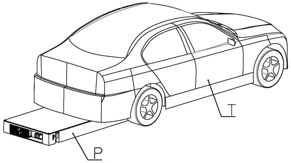
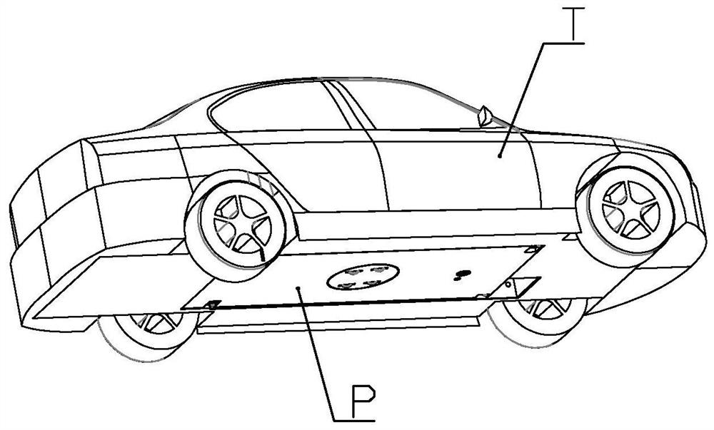
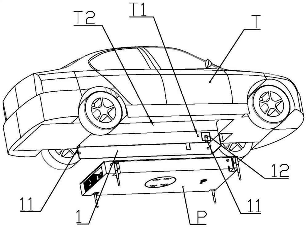
[0062] according to Figure 1 to Figure 12 As shown, this embodiment is a new energy electric vehicle, which includes a vehicle body T, and a battery unit P in the shape of a rectangular sheet as a whole is detachably mounted on the lower end of the vehicle body.
[0063] The lower end of the vehicle body is provided with a battery installation slot T2 for accommodating the battery unit, and a battery unit is installed on the left side along the length direction of the vehicle body in the battery installation slot for connecting the battery unit to the battery installation slot when the battery unit is installed in the battery installation slot. The positioning baffle 1 aligned with the battery installation slot.
[0064] The front end of the left side wall in the battery installation groove is equipped with a baffle motor 12 that drives the positioning baffle to extend or retract; the two ends of the positioning baffle along the length direction of the car body are rotatably ...
Embodiment 2
[0092] This embodiment makes the following improvements on the basis of Embodiment 1: an upper connection capacitor cavity 211 is formed on the cover plate of the housing at a position different from that of the mobile car, and an upper connection capacitor cavity 211 is slidably installed in the upper connection capacitor cavity. Seat 6, the upper end of the upper connection seat is equipped with 2-3 annular upper connection electrodes 61 arranged concentrically; the upper end of the upper connection seat is equipped with a permanent magnet 62; the lower part of the upper connection seat The outer wall is connected with more than two limit heads 63, and the side wall of the upper connection capacitor cavity is formed with a sliding limit groove 2112 that is slidably connected with each of the limit heads; the side wall of the upper connection capacitor cavity is also formed with wiring Port 2111, the upper connection electrode is electrically connected to the battery controlle...
Embodiment 3
[0100] combine Figure 12 to Figure 21 As shown, this embodiment makes the following improvements on the basis of Embodiment 1 or 2: the battery unit is connected with a cooling assembly, and the cooling assembly includes a collector installed in the battery case for absorbing the heat emitted by the lithium battery. Heat pipes, radiators mounted on the sides of the battery cells, and cooling pumps that drive cooling fluid to circulate between the heat collector pipes and the radiators.
[0101] The rear end of the battery case is formed with a radiator installation cavity 25, and the cooling pump and radiator are installed in the radiator installation cavity.
[0102] The radiator includes a heat dissipation plate 82, a heat dissipation seat 83 and a water wheel seat 84 which are sealed and connected in sequence; a heat dissipation channel 831 is opened on the end surface of the heat dissipation seat facing the heat dissipation plate, and the heat dissipation channel is arran...
PUM
 Abstract
Description
Claims
Application Information
 - R&D
- Intellectual Property
- Life Sciences
- Materials
- Tech Scout
- Unparalleled Data Quality
- Higher Quality Content
- 60% Fewer Hallucinations
Browse by: Latest US Patents, China's latest patents, Technical Efficacy Thesaurus, Application Domain, Technology Topic, Popular Technical Reports.
© 2025 PatSnap. All rights reserved.Legal|Privacy policy|Modern Slavery Act Transparency Statement|Sitemap|About US| Contact US: help@patsnap.com


