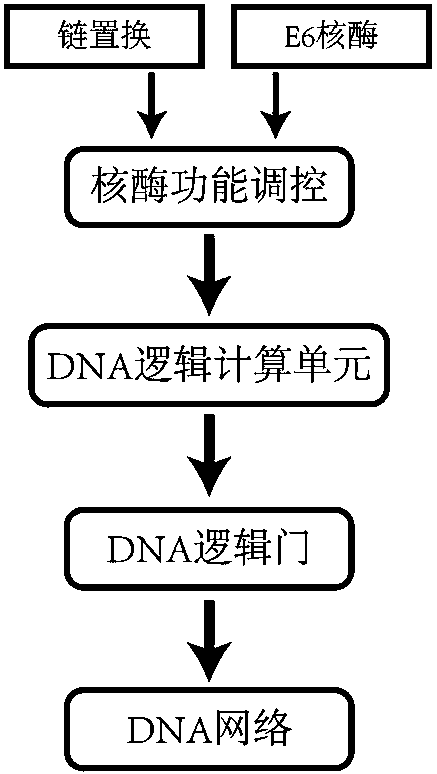
DNA network construction method for regulating and controlling E6 ribozyme function based on chain replacement
A construction method and strand replacement technology, applied in the field of biological computing, can solve problems such as aggravated leakage and DNA sequence interference, DNA enzymes not participating in logic computing units, difficulty in realizing modularization and large-scale DNA network construction, etc., and achieve structural stability Effect
- Summary
- Abstract
- Description
- Claims
- Application Information
AI Technical Summary
Problems solved by technology
Method used
Image
Examples
Embodiment 1
[0045] Embodiment 1 DNA YES logic gate
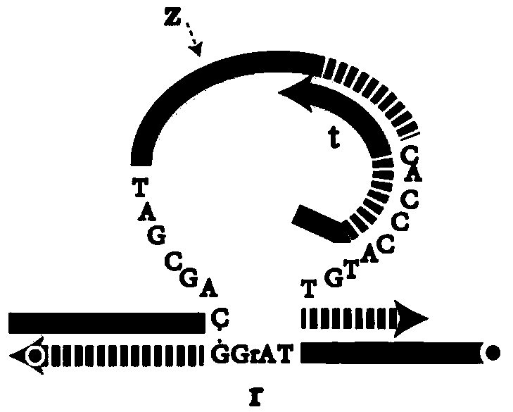
[0046] according to Figure 4 The construction method of the DNA YES logic gate in Figure 9 The analysis of the PAGE gel electrophoresis results of the YES logic gate is given. From the comparison of lane 1 and lane 2, the YES logic gate composed of sequences z1, t1, and r1 can be stably generated. Lane 3 shows the effect of E6 ribozyme on the RNA modification substrate Cutting effect of r1, when adding logic gate to trigger chain i1, YES logic gate gives correct output—chain o1 (lane 5). Figure 10 In order to correspond to the fluorescence detection result of the YES logic gate, compared with the fluorescence signal intensity when there is no input (Input=0), the fluorescence signal intensity of the YES logic gate is greatly enhanced (Output=1) when there is an input (Input=1) , indicating that the YES logic gate responds correctly to the input.
Embodiment 2
[0047] Embodiment 2 DNA OR logic gate
[0048] according to Figure 5 The construction method of DNA OR logic gate in Figure 11 It is the analysis of the PAGE gel electrophoresis results of the OR logic gate. By comparing the lanes 1 and 2, it can be known that the OR logic gate composed of the sequences z1, t2, and r1 can be stably generated. When trigger chains i2 (lane 5) and i3 (lane 5) and i3 (lane 6), the OR logic gate can output correctly, and when both input chains exist, the OR logic gate can also make a correct response (lane 7). Figure 12 It is the fluorescence detection result of the OR logic gate. Compared with the case of no input (Input=00), when the OR logic gate has any input (Input=10, 01, 11), the fluorescence signal intensity is greatly enhanced (Output=1), It shows that the OR logic gate can give correct calculation results for the four inputs of the OR operation.
Embodiment 3
[0049] Embodiment 3 DNA AND logic gate
[0050] according to Figure 6 The construction method of DNA AND logic gate in Figure 13 For the analysis of the PAGE gel electrophoresis results of AND logic gates, compare the electrophoresis bands of lane 1 and lane 2, and the AND logic gate composed of the sequence z2, t3, t4, r1 can be stably generated. When the AND gate has no input (lane 1), When there is only input i4 (lane 3) or only input i5 (lane 5), the E6 ribozyme z2 cannot cleave the substrate, that is, there is no output at this time. Enzyme z2 can cleave the substrate, and the output of the AND gate is 1 at this time. Figure 14 It is the fluorescence detection result of AND logic gate, when two inputs of AND logic gate all exist (Input=11), the intensity of fluorescence signal strengthens greatly (Output=1), and for other input situations (Input=00,01,10 ), and the intensity of the fluorescent signal weakens sharply (Output=0), which shows that the AND logic gate ca...
PUM
 Abstract
Description
Claims
Application Information
 - R&D
- Intellectual Property
- Life Sciences
- Materials
- Tech Scout
- Unparalleled Data Quality
- Higher Quality Content
- 60% Fewer Hallucinations
Browse by: Latest US Patents, China's latest patents, Technical Efficacy Thesaurus, Application Domain, Technology Topic, Popular Technical Reports.
© 2025 PatSnap. All rights reserved.Legal|Privacy policy|Modern Slavery Act Transparency Statement|Sitemap|About US| Contact US: help@patsnap.com


