Thermal barrier coating with thermal barrier and anti-CMAS corrosion attachment and preparation process of thermal barrier coating

A technology of thermal barrier coating and preparation process, which is applied in the direction of metal material coating process, coating, superimposed layer plating, etc., and can solve the problems of weakening the cooling effect of superalloys, clogging of cooling air film holes, and damage to metal substrates , to achieve the effect of reducing the depth and speed of vertical penetration, strong feasibility, and long-term stable operation

Active Publication Date: 2018-10-30
XI AN JIAOTONG UNIV
View PDF6 Cites 14 Cited by
  • Summary
  • Abstract
  • Description
  • Claims
  • Application Information

AI Technical Summary

Problems solved by technology

[0004] On the other hand, molten CMAS will accumulate near the cooling air film hole of the hot end components of the aero-engine, causing the cooling air film hole to be blocked, significantly weakening the cooling effect of the cooling gas on the superalloy, and causing severe ablation of the superalloy
Compared with the relatively "slow" corrosion of thermal barrier coatings by CMAS, the blockage of cooling air film holes caused by CMAS attachment will directly damage the metal substrate in a short time, which is undoubtedly more fatal

Method used


Image

  • Thermal barrier coating with thermal barrier and anti-CMAS corrosion attachment and preparation process of thermal barrier coating
  • Thermal barrier coating with thermal barrier and anti-CMAS corrosion attachment and preparation process of thermal barrier coating
  • Thermal barrier coating with thermal barrier and anti-CMAS corrosion attachment and preparation process of thermal barrier coating

Examples


Embodiment 1

[0034]A preparation process of a thermal barrier coating with both thermal barrier and anti-CMAS corrosion adhesion, comprising the following steps:

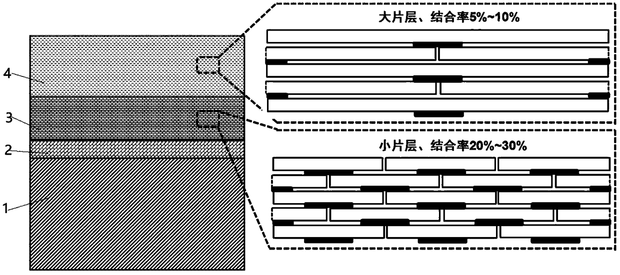
[0035] On the surface of the superalloy substrate and its bonding layer, use 8YSZ spray powder with a particle size of 45 μm to 75 μm, and spray through atmospheric plasma technology to prepare a layered ceramic heat insulation layer with a bonding rate of 25% to 30% and a thickness of 100 μm; heat insulation The laminar unit of the layer has a lateral dimension of 8 to 20 μm and a longitudinal dimension of 0.8 to 2.5 μm. Then, lanthanum zirconate powder (LZO) with a particle size of 50 μm to 100 μm was used to prepare a layered ceramic anti-CMAS corrosion adhesion layer by atmospheric plasma spraying; The thickness is 0.8-2.5 μm, and the bonding rate of adjacent sheet units along the thickness direction of the thermal barrier coating is 5%-10%. In the process of preparing the anti-CMAS corrosion adhesion layer by spraying, the...


PUM

PropertyMeasurementUnit
sizeaaaaaaaaaa
sizeaaaaaaaaaa
particle diameteraaaaaaaaaa

Abstract

The invention discloses a thermal barrier coating with a thermal barrier and an anti-CMAS corrosion attachment and a preparation process of the thermal barrier coating. The thermal barrier coating isof a double-layer structure and comprises the anti-CMAS corrosion adhesive layer and a thermal insulating layer. The thickness of the thermal insulating layer close to a base body is 30%-60% of the total thickness of the thermal barrier coating, and the thickness of the anti-CMAS corrosion adhesive layer close to thermal current is 40%-70% of the total thickness of the thermal barrier coating. Thethermal insulating layer and the anti-CMAS corrosion adhesive layer are both formed by stacking sheet layers. The sheet layers of the anti-CMAS corrosion adhesive layer can be peeled layer by layer.In the service process of the coating, by means of the large stacked sheet layers, the permeating path of CMAS is obviously increased, the speed of permeating along surface defects of the CMAS is delayed, and the anti-CMAS corrosion capacity of the coating is improved; and on the other hand, the film thermal mismatch stress generated by the temperature change can trigger local layer peeling of theanti-CMAS corrosion adhesive layer, therefore CMAS sediment adhering to the surface of the thermal barrier coating can be removed so that air film hole blockage caused by deposition, near air film holes, of the CMAS can be removed, and the long-time service stability of aero-engine hot end metal components can be greatly improved.

Description

technical field [0001] The invention belongs to the technical field of coatings, in particular to a thermal barrier coating. Background technique [0002] As the heart of the aircraft, the performance of the engine will directly affect various indicators of the aircraft performance, and one of the parameters that can best reflect the performance of the engine is the thrust-to-weight ratio. The goal pursued by modern aero-engines is to continuously increase the thrust-to-weight ratio and reduce service costs. The increase of the thrust-to-weight ratio will inevitably require a further increase in the temperature before the engine turbine. At present, the temperature in front of the turbine has far exceeded the metal material of the hot end component. Therefore, coating the thermal barrier coating with low thermal conductivity on the surface of the hot-end metal components and designing an advanced cooling system are the keys to ensure the stable operation of the hot-end met...

Claims


Application Information

Patent Timeline
Patent Type & Authority Applications(China)
IPC IPC(8): C23C4/11C23C4/10C23C4/134
CPCC23C4/10C23C4/11C23C4/134C23C28/042
Inventor 杨冠军李广荣刘梅军唐春华刘宏李成新李长久
Owner XI AN JIAOTONG UNIV
Why Eureka
Try Eureka