Internal combustion engine supercharging system integrated with waste heat recovery

A waste heat recovery system and waste heat recovery technology, applied in the direction of internal combustion piston engines, combustion engines, mechanical equipment, etc., can solve problems such as undiscovered technical solutions, achieve energy conservation and emission reduction, energy security, improve power and economy, and significantly economical The effect of benefits and application prospects

Inactive Publication Date: 2018-10-30
TIANJIN UNIV
View PDF7 Cites 4 Cited by
  • Summary
  • Abstract
  • Description
  • Claims
  • Application Information

AI Technical Summary

Problems solved by technology

Through the search and analysis of related patents at home and abroad, the applicant did not find a technical solution similar to the characteristics of the present invention

Method used


Image

  • Internal combustion engine supercharging system integrated with waste heat recovery
  • Internal combustion engine supercharging system integrated with waste heat recovery
  • Internal combustion engine supercharging system integrated with waste heat recovery

Examples


Embodiment 1

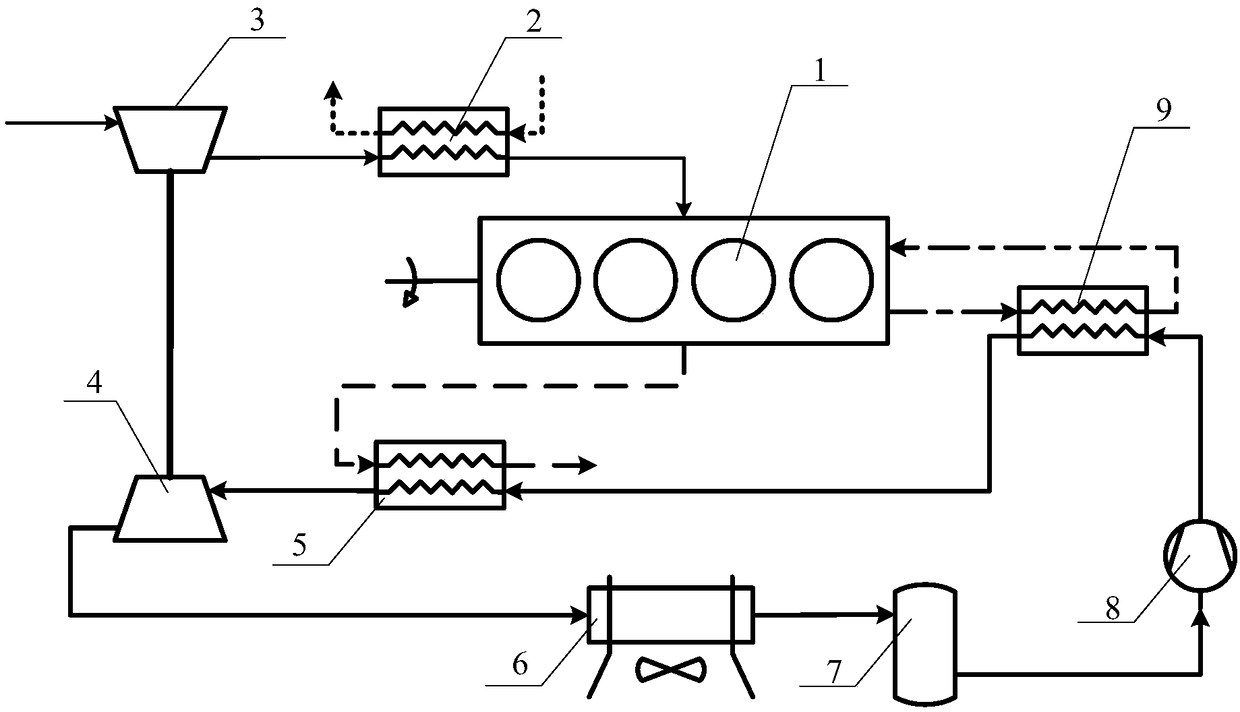
[0026] like figure 1 As shown, the present invention proposes an internal combustion engine supercharging system integrating waste heat recovery, including an internal combustion engine 1, an intercooler 2, a compressor 3 and a turbocharger 4, and the turbocharger 4 is the same as the compressor 3 The compressor 3 is connected to the internal combustion engine 1 through the charge air side of the intercooler 2, and the turbocharger 4 is driven by a waste heat recovery system based on Rankine Circulating power cycle system, including cooler 6, working medium tank 7, compressor 8, jacket water heat exchanger 9, flue gas heat exchanger 5 connected in series, the outlet of the compressor 8 is connected to the cylinder The working medium side inlet of the jacket water heat exchanger 9, the working medium side outlet of the jacket water heat exchanger 9 is connected to the working medium side inlet of the flue gas heat exchanger 5, and the flue gas heat exchanger 5 The outlet on th...

Embodiment 2

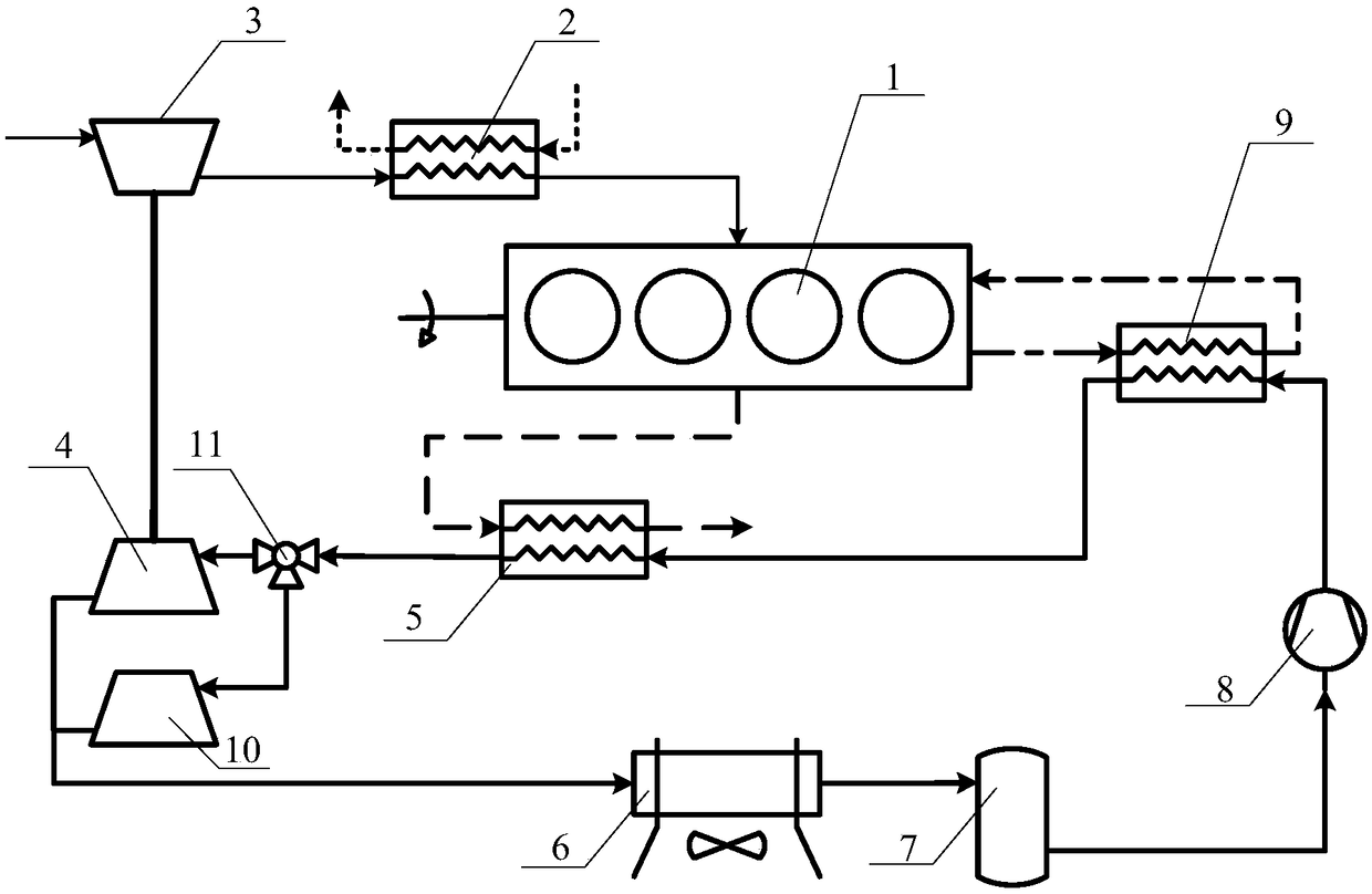
[0030] like figure 2 As shown, embodiment 2 adds an expander 10 on the basis of embodiment 1, that is, a three-way solenoid valve 11 is provided on the pipeline between the flue gas heat exchanger 5 and the turbocharger 4, so A three-way is provided on the pipeline between the supercharging turbine 4 and the cooler 6, and an expander 10 is connected between the three-way solenoid valve 11 and the three-way through a connecting pipeline. In this embodiment, in order to make full use of the exhaust energy of the internal combustion engine, by adding a three-way solenoid valve 11 and an expander 10, the system is divided into a supercharging branch realized by the turbocharger 4 and a power split realized by the expander 10. In this way, the exhaust energy that meets the supercharging needs of the internal combustion engine is converted into output work or electric energy or used as auxiliary power for the vehicle.

[0031] Compared with Embodiment 1, the working process of the...

Embodiment 3

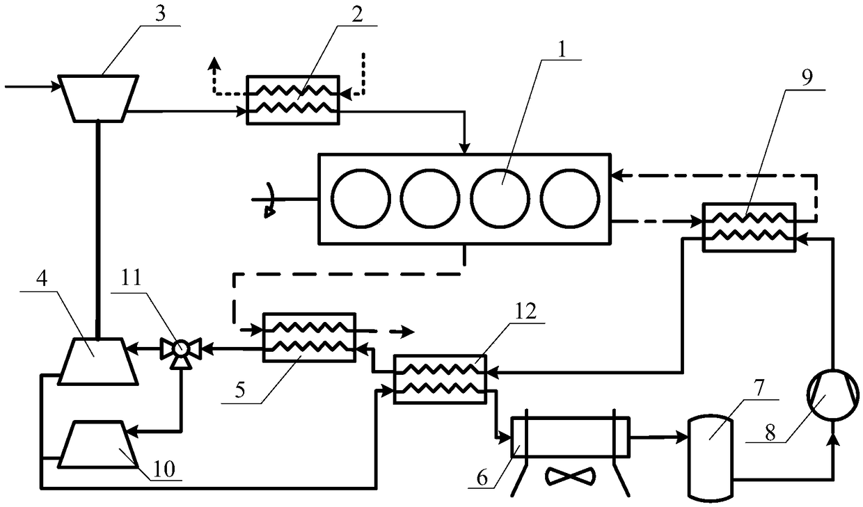
[0034] like image 3 As shown, in order to further recover the exhaust gas energy of the working medium after expansion, the embodiment 3 is based on the embodiment 2 and also includes an intermediate heat exchanger 12, and the outlet of the working medium side of the jacket water heat exchanger 9 passes through The high-pressure working medium side of the intermediate heat exchanger 12 is connected to the working medium-side inlet of the flue gas heat exchanger 5, and the outlet of the tee is connected after passing through the low-pressure working medium side of the intermediate heat exchanger 12 to the cooler 6.

[0035] Compared with Embodiment 2, the working process of the system in Embodiment 3 is only different: the low-pressure working fluid after the three-way confluence enters the intermediate heat exchanger 12 and the high-pressure working fluid at the outlet of the jacket water heat exchanger 9 to exchange heat and then enters the cooler 6.

[0036] The character...


PUM


Abstract

The invention discloses an internal combustion engine supercharging system integrated with waste heat recovery. The system takes waste heat of an internal combustion engine as an energy source, and realizes air intake supercharging of the internal combustion engine by integrating the internal combustion engine, a waste heat recovery system, a supercharging turbine and an intercooler. A high temperature and high pressure working medium after absorbing the waste heat of the internal combustion engine drives the supercharging turbine to do work and drives a coaxially connected compressor to realize the air intake supercharging. The high temperature and high pressure working medium can also be divided into two paths by a three-way solenoid valve to realize the air intake supercharging, and theexcess energy is used to do work for power generation or to drive the waste heat recovery system compressor or as auxiliary power of a vehicle. The system makes full use of the waste heat energy of the internal combustion engine to achieve greater output power of the internal combustion engine, can significantly improve the power and fuel utilization of the internal combustion engine, is high insystem integration degree, and has significant economic benefit, social benefit and application prospects.

Description

technical field [0001] The invention belongs to the field of thermal energy and power, in particular to an internal combustion engine supercharging system integrated with waste heat recovery. Background technique [0002] With the increasingly prominent energy issues and increasingly stringent emission regulations, it is becoming more and more important to achieve high efficiency, miniaturization, and low fuel consumption of internal combustion engines. [0003] The maximum power that an internal combustion engine can emit is limited by the actual amount of air inhaled into the cylinder per cycle. Turbocharging technology can greatly increase the output power of the internal combustion engine by utilizing the exhaust energy of the internal combustion engine while maintaining the same displacement, or enable the internal combustion engine to achieve The displacement required for the same output power is smaller. Traditional turbochargers usually use an exhaust bypass valve t...

Claims


Application Information

Patent Timeline
IPC IPC(8): F02B37/00F02B39/00F01N5/02F01N13/00
CPCF01N5/02F01N13/00F02B37/00F02B39/00Y02T10/12
Inventor 李晓雅舒歌群田华李君峰
Owner TIANJIN UNIV
Why Eureka
Try Eureka