

Self-powered valve adjustable in pressure difference for surgery department
An adjustable and autologous technology, applied in the direction of valves, wound drainage devices, etc., can solve the problems of inaccurate pressure setting, cumbersome pressure regulation process, and patient pain.
- Summary
- Abstract
- Description
- Claims
- Application Information
AI Technical Summary
Problems solved by technology
Method used
Image

Examples
Embodiment approach 1
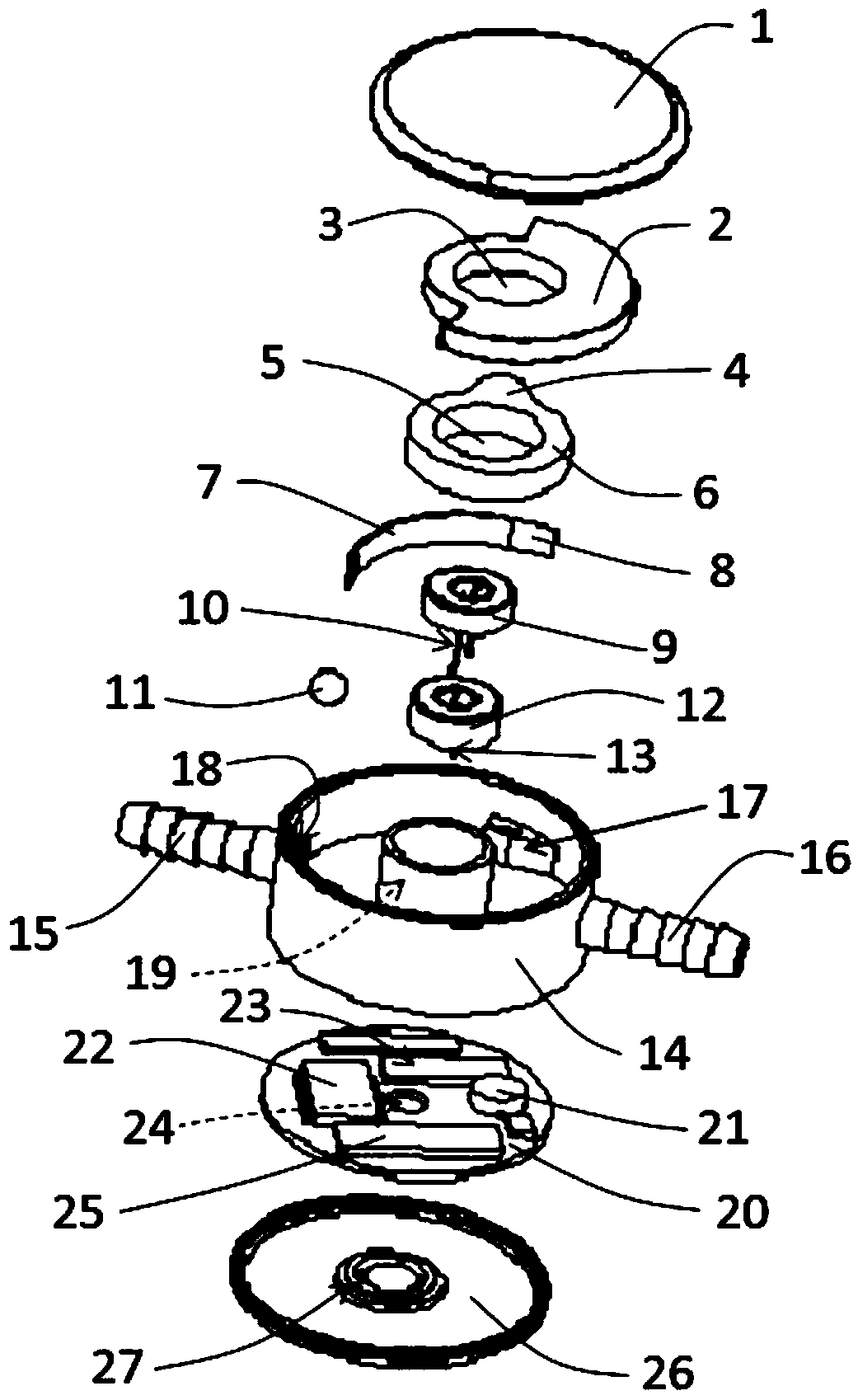
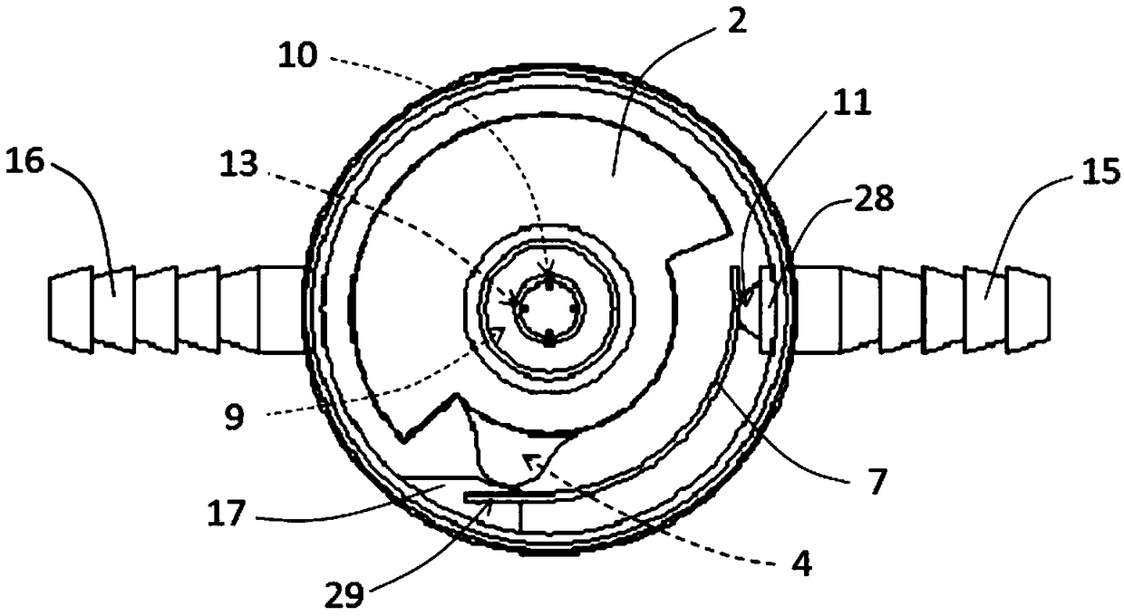
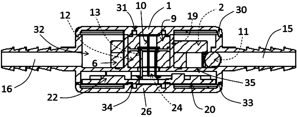
[0040] The autogenous energy conversion and storage process of the device: as attached Figure 1-3 As shown, after the device of the present invention is implanted into the human body, because the position of the human body is constantly changing, and the gravity kinetic energy pendulum (2) center of gravity is not at the same point as the center of circle, when the body position changes, its center of gravity always moves to the lowest position. Position rotation, as the rotor part of the permanent magnet electromagnetic induction generator of the device, when the position of the human body changes, it rotates around the part of the generator stator (9), and then generates alternating current in the stator coil winding, and the integrated circuit ( 25) After the commutation and rectification, the electric energy is stored in the storage battery (21) on the integrated circuit board (20).
Embodiment approach 2
[0042] The pressure identification and pressure setting process of the device: as attached Figure 1-3 As shown, when the servomotor rotor protruding part (4) of the present invention is located at a certain position of the pressure shrapnel (7), the pressure shrapnel (7) is under pressure from the servomotor rotor protruding part (4), and it will The pressure shrapnel (7) deforms at the tail end (8) of the pressure shrapnel fixing part (17) of the casing, producing a "leverage" pressure change, which is received by the pressure sensor (29) and passed through the integrated circuit board (20 ) after being processed by the amplifier integrated circuit (23), it is sent to the data storage, emission and control integrated circuit (22), where the data is stored. When the pressure data at this time needs to be read, the external controller data storage, transmission and control integrated circuit (22) sends an instruction, and the pressure data information data is transmitted and r...
Embodiment approach 3
[0046] The direct pressure identification and pressure setting process of the device: as attached Figure 1-3 As shown, when the energy of the storage battery (21) is insufficient to supply the above-mentioned electronic devices to work, the following methods can be adopted for pressure identification and pressure setting. After the device of the present invention is implanted in the human body, X-ray inspection can be performed, and the servo motor rotor (6 ) is developed under X-ray, the position of the protruding portion (4) can be determined, the pressure is read, and the pressure identification process is completed. Afterwards, the target is set according to the pressure and the corresponding target is sent to the servo motor (12) through the pulse transmitter Pressure setting pulse frequency, the servo motor rotor (6) rotates to the corresponding position, and the pressure setting process is completed.
[0047] The pulse transmitter is a transmitter that can transmit dif...
PUM
 Abstract
Description
Claims
Application Information