Fixed structural member, rotary lifting device and semiconductor processing equipment

A fixed structure, rotating lifting technology, applied in the field of magnetron sputtering, can solve the problems of difficult installation and disassembly, damage to fragile materials, and heavy weight, so as to improve the speed of installation and disassembly, reduce the difficulty of installation and disassembly, and reduce the risk of damage Effect

Active Publication Date: 2018-11-02
BEIJING NAURA MICROELECTRONICS EQUIP CO LTD
View PDF4 Cites 0 Cited by
  • Summary
  • Abstract
  • Description
  • Claims
  • Application Information

AI Technical Summary

Problems solved by technology

[0006] The reaction chamber subsystem of the prior art 1 has the following defects: when installing and disassembling the rotating lifting mechanism 7, it takes a long time to bear against the rotating lifting mechanism 7, and the rotating lifting mechanism 7 is often relatively heavy, which causes great troubles for installation and disassembly. At the same time, once the force is relaxed, the rotating lifting mechanism 7 will fall or touch the fragile material, which will easily cause damage to the fragile material

Method used


Image

  • Fixed structural member, rotary lifting device and semiconductor processing equipment
  • Fixed structural member, rotary lifting device and semiconductor processing equipment
  • Fixed structural member, rotary lifting device and semiconductor processing equipment

Examples


Embodiment 1

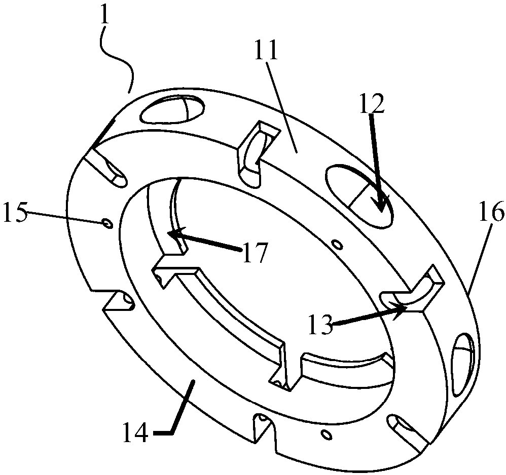
[0045] This embodiment provides a fixed structure, such as Figure 3-Figure 9 As shown, it includes a first ring structure 1, a second ring structure 2 and a connector 3, wherein the first ring structure 1 and the second ring structure 2 fit together to form a ring structure; the connector 3 is movably arranged on the first ring In structure 1, the second ring structure 2 can rotate relative to the first ring structure 1 to push the connecting member 3 to swing within a certain angle range, so as to fix or release the fixed object.

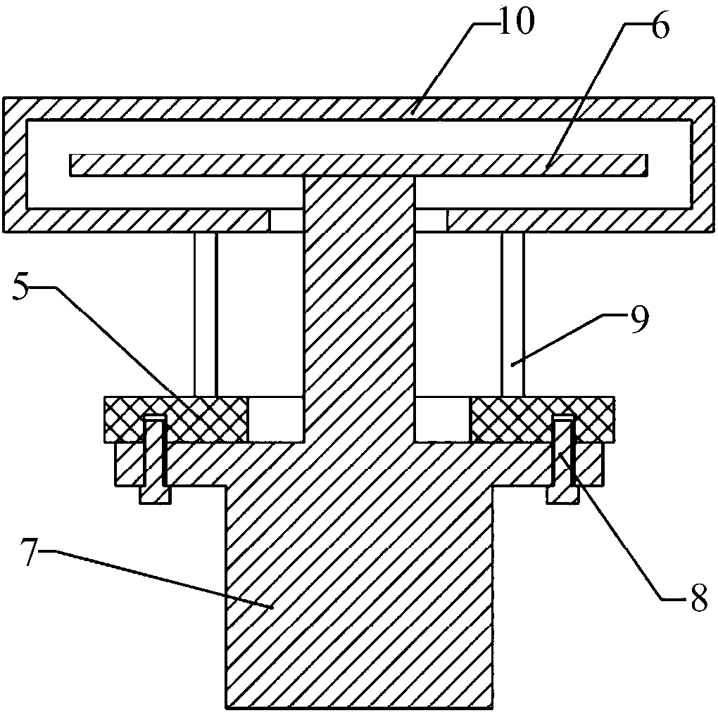
[0046] In this embodiment, the fixing structure is used to be installed on the flange 5 suspended on the bottom of the chamber 4, so as to fix or release the rotating lifting mechanism 7 that drives the tray 6 to rotate and lift. Swinging within a certain angle range can realize fixing or releasing fixing of the rotating lifting mechanism 7 . The fixed structural part can form a good load on the rotating lifting mechanism 7 before the connecting ...

Embodiment 2

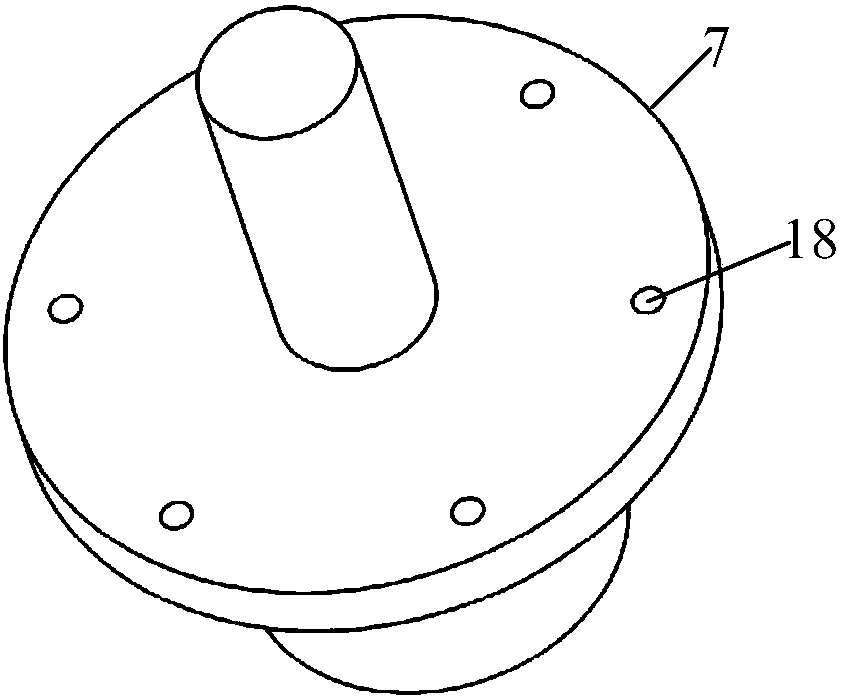
[0062] This embodiment provides a rotary lifting device, such as Figure 10 and Figure 11 As shown, it includes the rotating lifting mechanism 7 and the flange 5, and also includes the fixing structure 19 in Embodiment 1. The fixing structure 19 is arranged on the flange 5 for fixing and releasing the rotating lifting mechanism 7.

[0063] Among them, such as Figure 11 As shown, a plurality of fifth through holes 71 are provided on the edge of the end of the rotary lifting mechanism 7 for bonding with the lower surface of the flange 5 facing away from the bottom of the chamber 4, and the fifth through holes 71 are formed at the end. The edge is not closed; the fifth through hole 71 corresponds to the position of the second through hole 13, and when the first fixing rod 32 is parallel to the axis of the ring structure, it passes through the second through hole 13 and the fifth through hole 71, To fix the rotating lifting mechanism 7. When the first fixing rod 32 forms a se...

Embodiment 3

[0067] This embodiment provides a semiconductor processing equipment, including a chamber, the bottom of the chamber is provided with a tray, and also includes the rotating lifting device in Embodiment 2, the flange of the rotating lifting device is fixed on the bottom of the chamber through a support rod, and rotates The rotary lifting mechanism of the lifting device is fixed on the flange through the fixed structure, and the shaft of the rotary lifting mechanism used to drive the tray to rotate and lift passes through the inner ring of the fixed structure and enters the chamber, and contacts with the tray.

[0068] By adopting the rotary lifting device in Embodiment 2, the installation and disassembly speed of the semiconductor processing equipment is improved, thereby improving the maintenance efficiency of the semiconductor processing equipment.


PUM


Abstract

The invention provides a fixed structural member, a rotary lifting device and semiconductor processing equipment. The fixed structural member comprises a first annular structure, a second annular structure and a connecting piece, wherein the first annular structure and the second annular structure are laminated to form an annular structural member, and the connecting piece is movably arranged in the first annular structure. The second annular structure can rotate relative to the first annular structure so as to push the connecting piece to swing within a certain angle range to realize fixationor release for a fixed object. The fixed structural member forms good load bearing for a rotary lifting mechanism before the connecting piece releases fixation for the rotary lifting mechanism, thereby shortening the manual bearing time for the rotary lifting mechanism during mounting and dismounting, further reducing the mounting and dismounting difficulty of the rotary lifting mechanism, and reducing the risk of damage to fragile objects during mounting and dismounting the rotary lifting mechanism.

Description

technical field [0001] The invention relates to the technical field of magnetron sputtering, in particular to a fixed structure, a rotating lifting device and semiconductor processing equipment. Background technique [0002] The CVD (Chemical Vapor Deposition, chemical vapor deposition) method is a method for preparing epitaxial thin film layers by using different gases to react with each other at high temperature. Thin film epitaxial growth can be carried out by CVD equipment, that is, a single crystal layer that meets certain requirements and has the same crystal orientation as the substrate is grown on a single crystal substrate (substrate). Taking silicon epitaxy as an example, the chemical vapor deposition epitaxial growth of silicon epitaxy is based on the principle of transporting silicon compounds (SiHCl 3 or SiCl 4 or SiH 2 Cl 2 etc.), using hydrogen (H 2 ) A method of precipitating silicon on a substrate through a reduction reaction. [0003] The core compone...

Claims


Application Information

Patent Timeline
Patent Type & Authority Applications(China)
IPC IPC(8): C23C16/458
CPCC23C16/4584
Inventor 张峥
Owner BEIJING NAURA MICROELECTRONICS EQUIP CO LTD
Why Eureka
Try Eureka