
Hydrogen charging and discharging performance detection system for hydrogen storage tank

A detection system and hydrogen storage tank technology, which is applied in the field of hydrogen storage tank hydrogen charging and discharging performance detection system, can solve problems such as the inability to realize the detection of hydrogen charging performance, the detection of constant flow hydrogen charging performance, and the limitation of the temperature range of detection. , to achieve the effect of wide detection temperature range and increased boost pressure

Active Publication Date: 2018-11-02
GLOBAL ENERGY INTERCONNECTION RES INST CO LTD +2
View PDF9 Cites 5 Cited by
  • Summary
  • Abstract
  • Description
  • Claims
  • Application Information

AI Technical Summary

Problems solved by technology

[0006] The purpose of the present invention is to provide a system that can realize the test and evaluation of the hydrogen charging and discharging performance of the hydrogen storage tank under various detection conditions, which solves the problem that the existing technology cannot realize the detection of the hydrogen charging performance under constant pressure, constant flow charging, etc. The detection of hydrogen performance, and the problem that the temperature range of detection is limited

Method used


Image

  • Hydrogen charging and discharging performance detection system for hydrogen storage tank
  • Hydrogen charging and discharging performance detection system for hydrogen storage tank

Examples


Embodiment 1

[0065] Use the static chemical hydrogen compression and storage integrated machine T2 to boost the pressure:

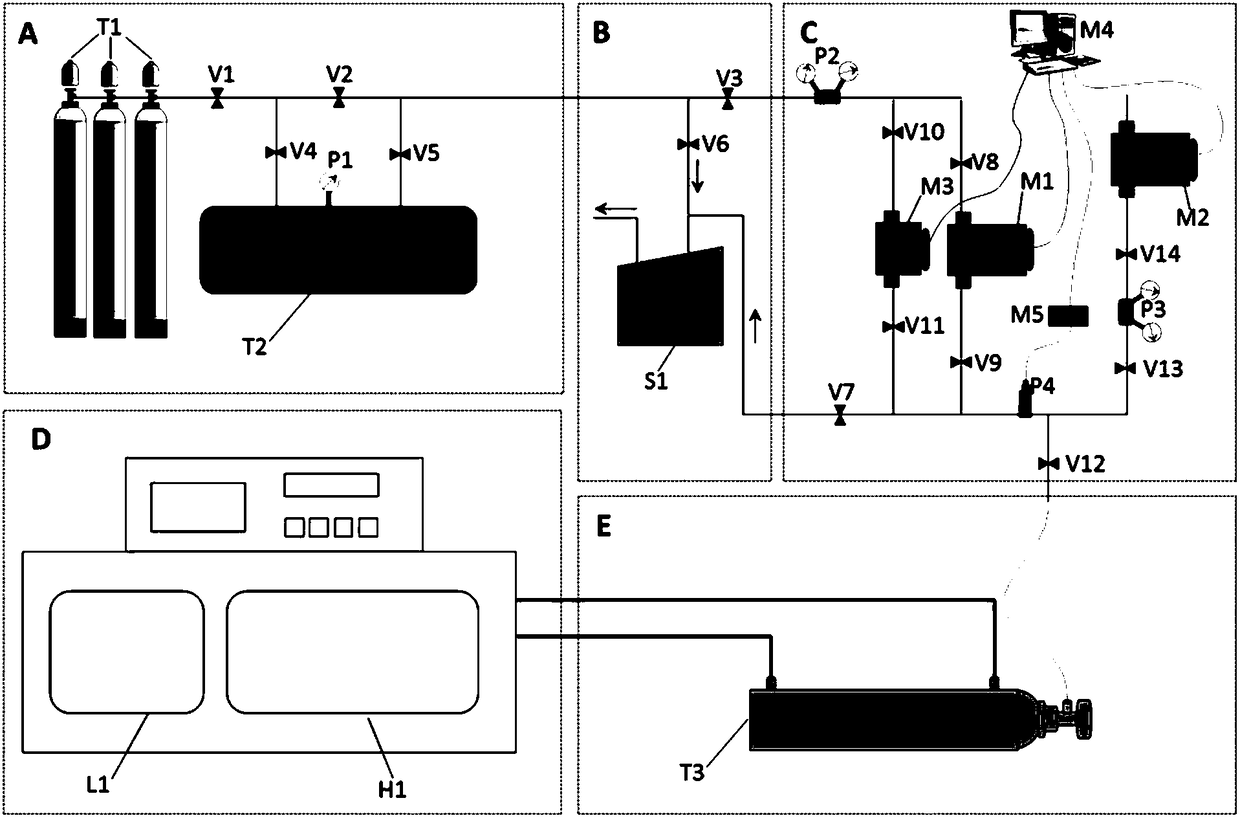
[0066] At room temperature, open the valves V1 and V4, close the valves V2 and V5, fill the low-pressure hydrogen in the hydrogen cylinder group T1 into the static chemical hydrogen compression and storage integrated machine T2, and close the valve V1 after the reading of the pressure gauge P1 is stable and V4, and keep the valve V5 closed, heating the static chemical hydrogen compression storage integrated machine T2, because the hydrogen plateau pressure of the metal hydride increases with the temperature, so after heating, the hydrogen in the static chemical hydrogen compression storage integrated machine T2 The pressure will rise slowly, and the boost level is related to the water temperature, hydrogen content and hydrogen storage materials.

Embodiment 2

[0068] Use the mechanical vacuum pump S1 to exhaust the hydrogen pipeline:

[0069] When the hydrogen cylinder T1 is replaced, close the valves V4, V5, V3 and V7, open the valves V1, V2 and V6, and turn on the mechanical vacuum pump S1 at the same time to remove the miscellaneous gas in the gas circuit; when the hydrogen storage tank T3 to be tested is replaced , then close the valves V11, V9, V13 and V6, open the valves V7 and V12, and at the same time turn on the mechanical vacuum pump S1 to remove the miscellaneous gas in the gas circuit.

Embodiment 3

[0071] Test the hydrogen charging and discharging performance of a hydrogen storage tank T3 to be tested:

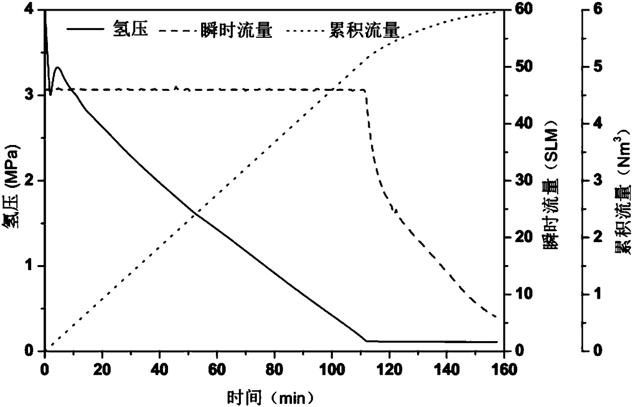
[0072] The rated hydrogen storage capacity of the hydrogen storage tank T3 to be tested is 5Nm 3 , the rated hydrogen filling pressure is 4MPa, and the heat exchange is carried out by means of external heat exchange.

[0073] 1. Test preparation.

[0074] Connect the hydrogen storage tank T3 to be tested to the test system, close the valves V11, V9, V13 and V6, open the valves V12 and V7, and at the same time turn on the mechanical vacuum pump S1 to vacuum the gas path to discharge impurity gases. After the exhaust is completed, close each Valves and mechanical vacuum pump S1.

[0075] Connect the cylinder T1 filled with hydrogen to the test system, close the valves V4, V5, V3 and V7, open the valves V1, V2 and V6, and at the same time turn on the mechanical vacuum pump S1 to evacuate the gas path to discharge impurity gases. After the exhaust is completed, Close all ...


PUM


Abstract

The invention discloses a hydrogen charging and discharging performance detection system for a hydrogen storage tank. The hydrogen charging and discharging performance detection system comprises a hydrogen source module (A), an exhaust module (B), a measuring and recording module (C), a cold-heat source module (D) and a to-be-detected area (E). The hydrogen source module (A) is provided with a main pipeline initial segment, a main pipeline middle segment and a main pipeline tail segment, wherein the main pipeline initial segment, the main pipeline middle segment and the main pipeline tail segment are connected in the direction from the hydrogen source module (A) to the to-be-detected area (E). The hydrogen charging and discharging performance detection system for the hydrogen storage tankcan perform constant-pressure hydrogen charging and constant-flow hydrogen charging detection, and the utilization rate of steel cylinder hydrogen gas is increased; and meanwhile, the hydrogen sourcepressure can be stabilized at a high level, and the detection temperature range of the detection system can be expanded to -40-300 DEG C. The hydrogen charging and discharging performance detection system for the hydrogen storage tank provided by the invention is simple in structure, diversified in function and wide in detection temperature range, and the hydrogen utilization rate of a hydrogen source is high.

Description

technical field [0001] The invention relates to the field of hydrogen storage performance testing, in particular to a detection system for hydrogen charging and discharging performance of a hydrogen storage tank. Background technique [0002] Due to its advantages of cleanliness, high calorific value and various uses, hydrogen energy is regarded as an ideal secondary energy source. However, the large-scale application of hydrogen energy needs to solve key technical problems such as large-scale and cheap production, storage and utilization of hydrogen. The bottleneck of large-scale utilization of hydrogen energy is the storage problem. According to the form of hydrogen, hydrogen storage methods include high-pressure gaseous hydrogen storage, low-temperature liquid hydrogen storage and solid-state hydrogen storage. Among them, solid-state hydrogen storage is a hydrogen storage method that uses the hydrogenation / dehydrogenation reaction of hydrogen storage materials to realize...

Claims


Application Information

Patent Timeline
Patent Type & Authority Applications(China)
IPC IPC(8): F17C13/02
CPCF17C13/02F17C13/025F17C2250/043Y02P90/45Y02E60/32
Inventor 刘海镇徐丽盛鹏刘双宇赵广耀王博马光韩钰陈新
Owner GLOBAL ENERGY INTERCONNECTION RES INST CO LTD
Learn More