
Manufacturing method of vacuum pressure impregnated stator bar for air-cooled hydroelectric generator

A vacuum pressure impregnation and stator bar technology, which is applied in the manufacture of motor generators, electromechanical devices, electrical components, etc., can solve the problems of increasing the cross-sectional size of wires, making it difficult to ensure that the drawing requirements are met, and the insulation thickness is difficult to achieve a wide range of applications. The effect of applying the foreground

Active Publication Date: 2020-09-08
HARBIN ELECTRIC MASCH CO LTD
View PDF4 Cites 0 Cited by
  • Summary
  • Abstract
  • Description
  • Claims
  • Application Information

AI Technical Summary

Problems solved by technology

In addition, the increase of the rated voltage increases the insulation thickness of the VPI stator bar and increases the cross-sectional size of the wires. There are still the following technical problems in the manufacturing process: it is difficult to ensure that the straight line corners of the wires and the negative wire corners meet the requirements of the drawings, and the insulation thickness is relatively large. It is difficult to penetrate the impregnating varnish, and the curing performance of the insulating layer is difficult to control, etc.

Method used


Image

  • Manufacturing method of vacuum pressure impregnated stator bar for air-cooled hydroelectric generator
  • Manufacturing method of vacuum pressure impregnated stator bar for air-cooled hydroelectric generator
  • Manufacturing method of vacuum pressure impregnated stator bar for air-cooled hydroelectric generator

Examples


Embodiment Construction

[0030]The invention relates to a manufacturing method of a vacuum pressure impregnated stator wire rod of an air-cooled water turbine generator. The VPI stator wire rod is composed of a straight part and two ends.

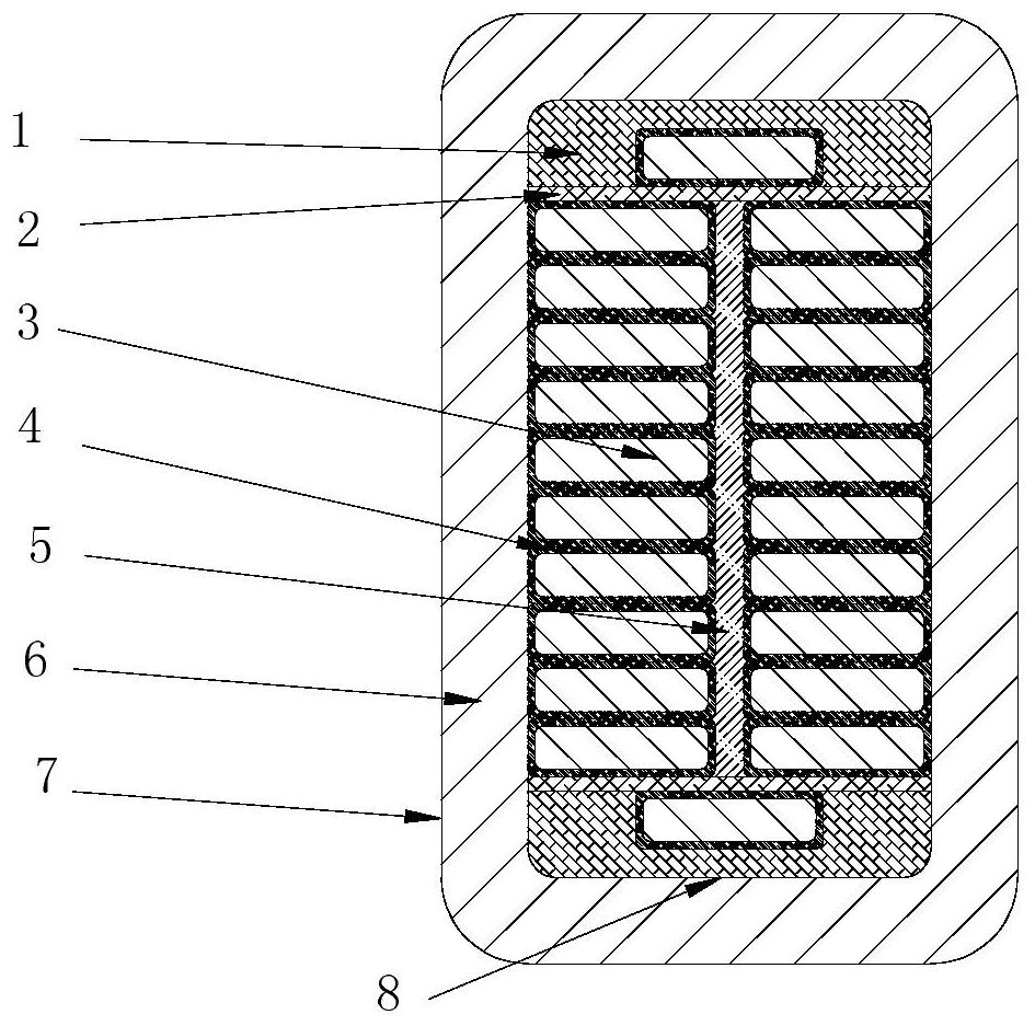
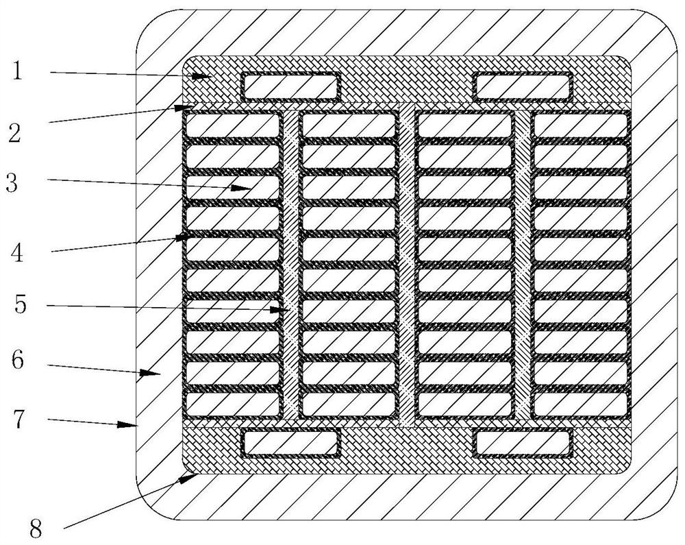
[0031] straight line (such as figure 1 or image 3 shown), including: wire narrow surface insulation pad (1), transposition insulation layer (2), wire composed of magnet wire (3), insulation between wire rows (5), main insulation layer of wire bar (6) , low-resistance anti-corona layer (7), inner shielding layer (8);

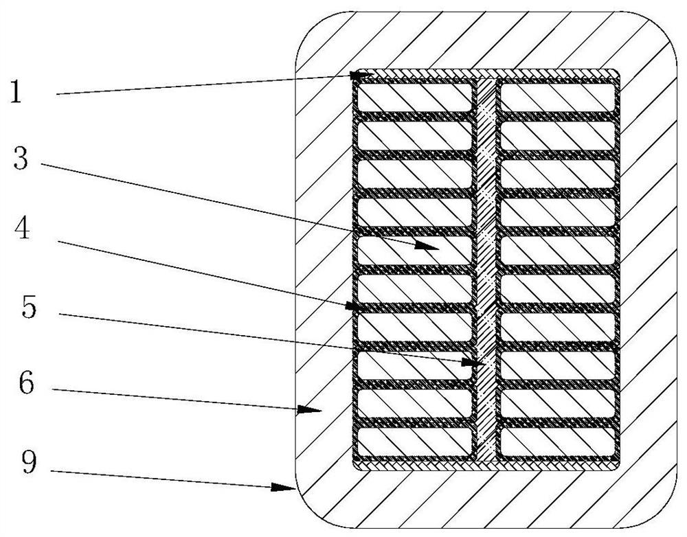
[0032] end (eg figure 2 or Figure 4 (shown) includes: wire narrow surface insulating pads (1), two or four rows of wires composed of electromagnetic wires (3), insulation between wire rows (5), main insulation layer of wire rods (6), anti-corona at the end layer(9);

[0033] Wire rod bonding structure (such as Figure 1 ~ Figure 4 (shown) is: wire narrow surface insulating gasket (1) not only fills the transposition pits on the narrow surface...


PUM

PropertyMeasurementUnit
lengthaaaaaaaaaa

Abstract

The invention relates to a manufacturing method of an air-cooled unit capacity hydrogenerator VPI (Vacuum Pressure Impregnating) stator coil bar. An inner shielding layer on the surface of a wire canreduce an internal local discharge probability of the wire. After the coil bar is bound with a VPI main insulation layer, a straight-line segment is bound in a half-lapping mode with a layer of low-resistance anti-corona material, then VPI of epoxy anhydride resin is carried out, after impregnation is ended, the end part is respectively bound in a half-lapping mode with medium resistance, medium-high resistance and high resistance segments, and the surface of an anti-corona segment of the end part is bound with two layers of additional insulation layers; after an anti-corona layer is processedwell, the coil bar is assembled into a hot-pressing die, pressurization is carried out, and the coil bar is placed into a baking oven to carry out heating, curing and forming; and after the main insulation layer is cured and formed, a protection layer is brushed with a high-resistance anti-corona paint and a surface coating varnish so as to obtain the finished product VPI stator coil bar. The air-cooled unit capacity hydrogenerator VPI stator coil bar has the main technical performance indexes that: (1) a breakdown voltage of the finished product coil bar is greater than or equal to 5.5UN; and (2) an electrical aging resistance experiment of the coil bar shows that the service life under a voltage of 3.0UN is greater than 40H, and the service life under a voltage of 2.0UN is greater than1,100h.

Description

Technical field: [0001] The invention relates to a method for manufacturing an air-cooled water turbine generator vacuum pressure impregnated stator wire rod. Background technique: [0002] Vacuum Pressure Impregnating (VPI) insulation system is one of the two main insulation systems in the world. At present, foreign countries have manufactured VPI stator bars with a rated voltage of 22kV and a stand-alone capacity of 800MW. This is the hydroelectric unit with the largest capacity and the highest rated voltage in the world. Flashover, corona, overheating and other problems often occur in the halo part, and the test needs to be installed with a shunt device. There are a large number of stator wire rods for large hydroelectric generators. Generally, there are at least more than 1,000 wire rods per unit. Installing a shunt device for AC withstand voltage test requires a large test workload and long operation time, which affects the production cycle. The VPI stator bar of the ...

Claims


Application Information

Patent Timeline
Patent Type & Authority Patents(China)
IPC IPC(8): H02K15/12
CPCH02K15/12
Inventor 付强陈庆国孙永鑫张秋寒黄程韦冯超郑伟姜禹管少博
Owner HARBIN ELECTRIC MASCH CO LTD
Learn More