
A device for measuring radiation magnification in orthopedics

A measuring device and magnification technology, which is applied in the field of medical equipment, can solve problems such as doctor's lesion diagnosis error, inconstant magnification ratio, delayed treatment, etc., and achieve the effects of ensuring clarity, avoiding distortion and deformation, and being convenient to use

Active Publication Date: 2022-04-15
张兆斌
View PDF6 Cites 0 Cited by
  • Summary
  • Abstract
  • Description
  • Claims
  • Application Information

AI Technical Summary

Problems solved by technology

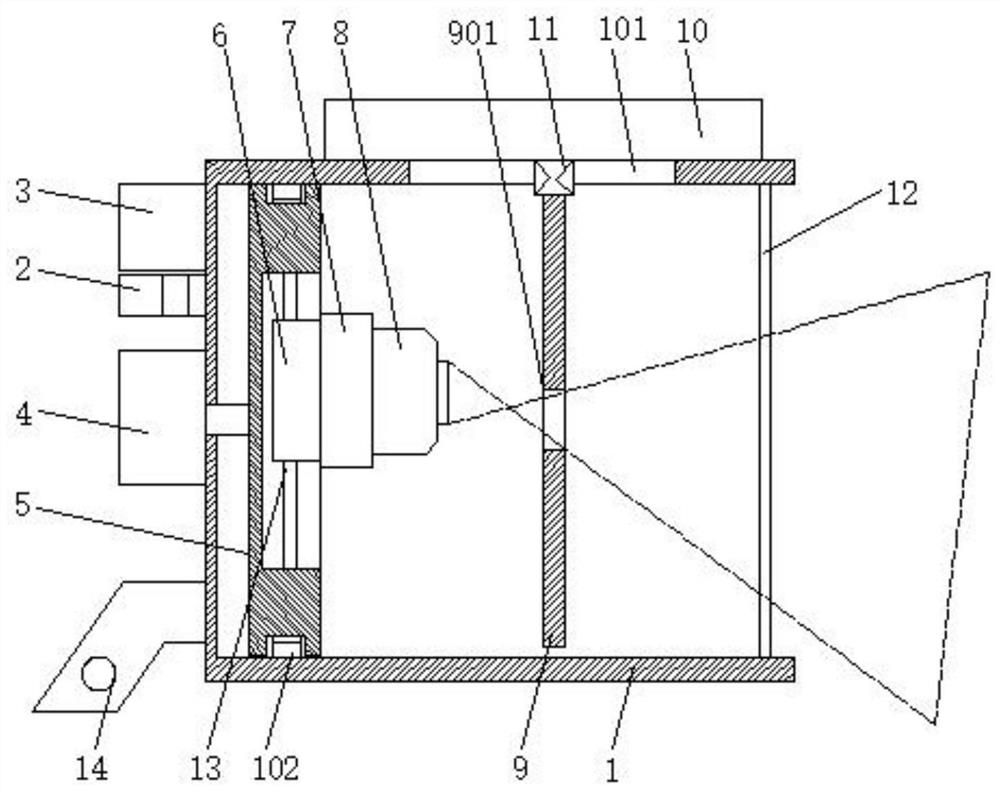
[0002] When diagnosing a disease, doctors need to measure the size of the lesion or estimate the size of the implant to help make a correct diagnosis and perform surgical planning. Therefore, the accuracy of the calculation of the original body value of the bone structure is required to increase, and The calculation of these values ​​is mainly obtained indirectly through X-ray photography images. How to provide accurate image data for clinical use and obtain accurate image magnification is the key. The X-ray films currently taken are those in the central ray, although There is magnification, but the original shape of the subject is still maintained, and there is no image distortion or distortion. However, due to oblique projection, the X-ray image of the marginal ray is both magnified and distorted for the subject. Constant, there is an error in the measurement, which may lead to errors in the diagnosis of the lesion by the doctor and delay in treatment

Method used


Image

  • A device for measuring radiation magnification in orthopedics

Examples


Embodiment Construction

[0012] The following will clearly and completely describe the technical solutions in the embodiments of the present invention with reference to the accompanying drawings in the embodiments of the present invention. Obviously, the described embodiments are only some, not all, embodiments of the present invention. Based on the embodiments of the present invention, all other embodiments obtained by persons of ordinary skill in the art without making creative efforts belong to the protection scope of the present invention.

[0013] see figure 1 , the present invention provides a technical solution: a measuring device for orthopedic radiation magnification, comprising a housing 1, a fixing plate 14 is fixed on the left end surface of the housing 1, and a reserved hole is provided in the middle of the fixing plate 14, and the housing 1 A PLC controller 2, a storage battery 3 and a stepping motor 4 are installed outside the left end face of the housing 1, the output shaft of the step...


PUM


Abstract

The invention discloses a measuring device for orthopedic radiation magnification, which comprises a casing, a PLC controller, a storage battery and a stepping motor are installed on the outside of the left end face of the casing, and the output shaft of the stepping motor passes through the casing The shaft hole in the middle of the right end face, this device for measuring radiation magnification in orthopedics, has a simple structure and is easy to use. The X-ray magnification can be changed by moving the optical hole. To ensure the clarity of the image under certain circumstances, the X-ray machine probe can move along the diameter direction of the mounting plate, and can rotate with the mounting plate at the same time, and reduce the inclination after X-ray radiation under the condition of constant magnification to avoid tilting The position of the edge of the image is distorted and deformed by the emission, and the image stack of the same detection level is performed from multiple angles, and the lesion is detected clearly and intuitively under the condition of a constant magnification ratio, with small errors, which is conducive to subsequent treatment.

Description

technical field [0001] The invention relates to the technical field of medical devices, in particular to a device for measuring radiation magnification in orthopedics. Background technique [0002] When diagnosing a disease, doctors need to measure the size of the lesion or estimate the size of the implant to help make a correct diagnosis and perform surgical planning. Therefore, the accuracy of the original body numerical calculation of the bone structure is required to increase, and The calculation of these values ​​is mainly obtained indirectly through X-ray photography images. How to provide accurate image data for clinical use and obtain accurate image magnification is the key. Currently, the X-ray films taken at the center of the X-ray image, although There is magnification, but the original shape of the subject is still maintained, and there is no image distortion or distortion. However, the X-ray image of the marginal ray is both enlarged and distorted due to oblique...

Claims


Application Information

Patent Timeline
Patent Type & Authority Patents(China)
IPC IPC(8): A61B6/00
CPCA61B6/58
Inventor 张兆斌张明张丽
Owner 张兆斌
Learn More