
A kind of SCR industrial flue gas denitrification method

An industrial flue gas and denitrification technology, applied in the field of flue gas denitrification, can solve the problems of easy generation of swirl layer, unfavorable flue gas denitrification, uneven mixing of flue gas and ammonia gas, etc.

Active Publication Date: 2020-10-23
武汉凤凰绿色贸易有限公司
View PDF5 Cites 0 Cited by
  • Summary
  • Abstract
  • Description
  • Claims
  • Application Information

AI Technical Summary

Problems solved by technology

[0004] This technical solution realizes the mixing of ammonia and NOx by generating two-stage swirling catalytic reduction reaction, which can improve the mixing of ammonia and NOx to a certain extent; The degree of mixing is limited. At the same time, when ammonia gas and flue gas generate swirling flow, it is easy to generate a swirling layer, and part of the flue gas and ammonia gas will not mix very uniformly, which is not conducive to the progress of flue gas denitrification.

Method used


Image

  • A kind of SCR industrial flue gas denitrification method
  • A kind of SCR industrial flue gas denitrification method
  • A kind of SCR industrial flue gas denitrification method

Examples


Embodiment approach

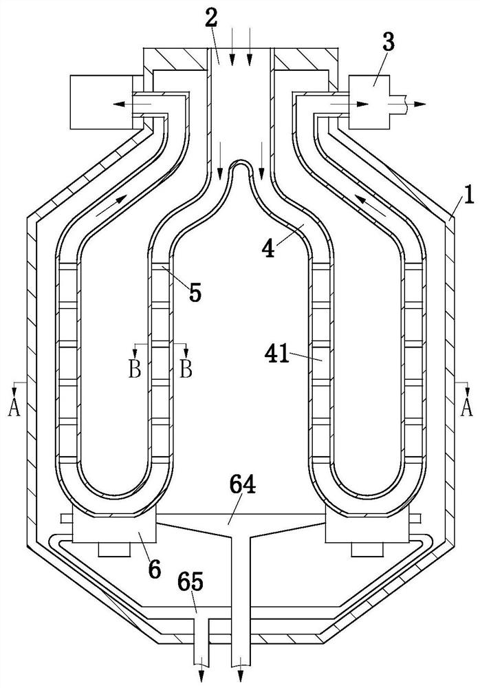
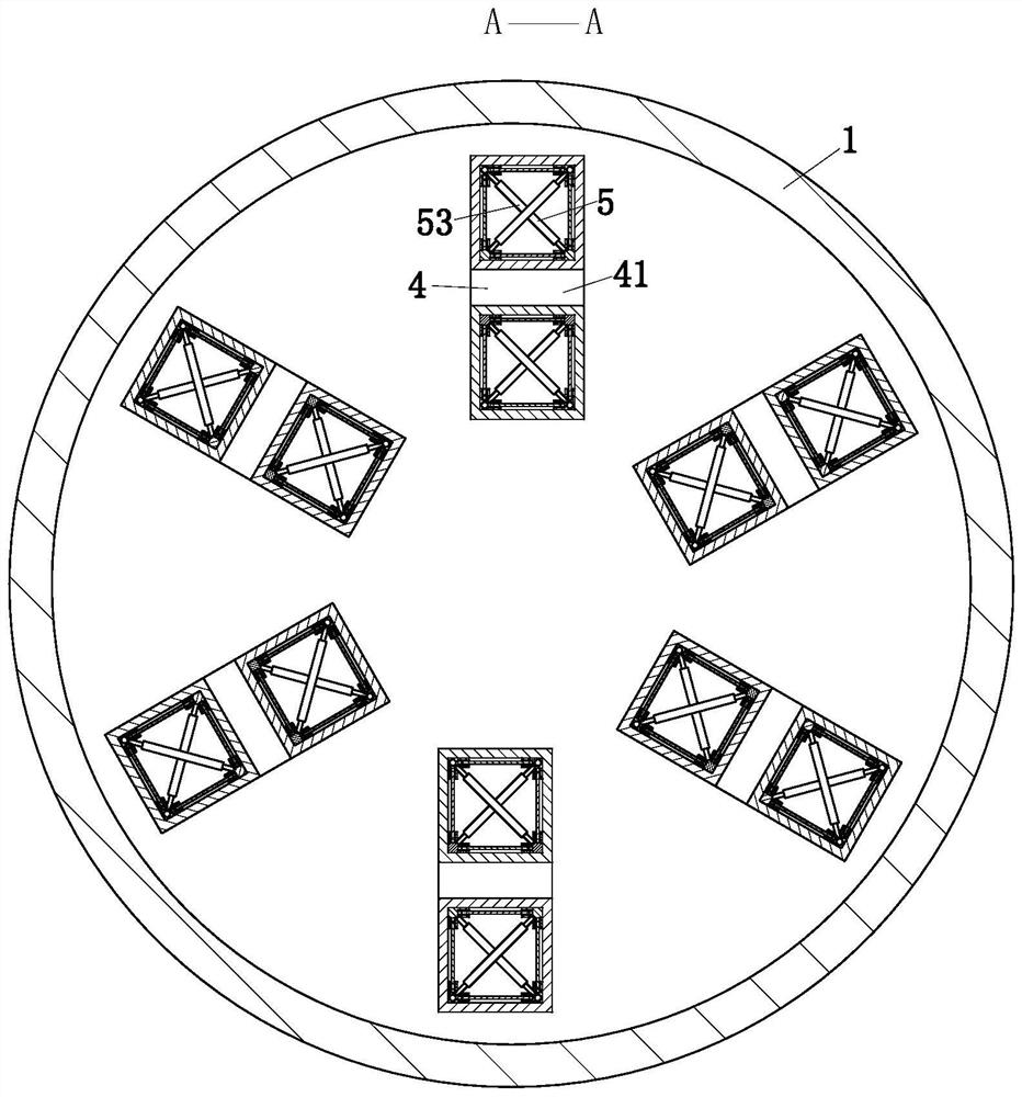
[0040] As an embodiment of the present invention, the ammonia injection module 5 includes a fixed frame 51, a shower 53 and a catalytic plate 54; the fixed frame 51 is a right-angled V-shaped, and the fixed frame 51 includes a fixed frame one 52 and Fixed frame two 522; the fixed frame one 52 is located at two adjacent corners of the sub-circulation pipe 41, the fixed frame two 522 is located at the other two adjacent corners of the sub-circulation pipe 41, and the diagonal fixed frame one 52 and the fixed frame two 522 are located on the same horizontal plane, and the first fixed frame 52 is provided with a spray interface 521; the sprinklers 53 are arranged on the diagonal fixed frame one 52 and the second fixed frame 522, and the sprayers 53 are equidistantly intersected. One end of the shower 53 communicates with the spray interface 521; the catalytic plate 54 is located between the adjacent fixing frames 51, the catalytic plate 54 is in the shape of a block, and a catalyst...


PUM


Abstract

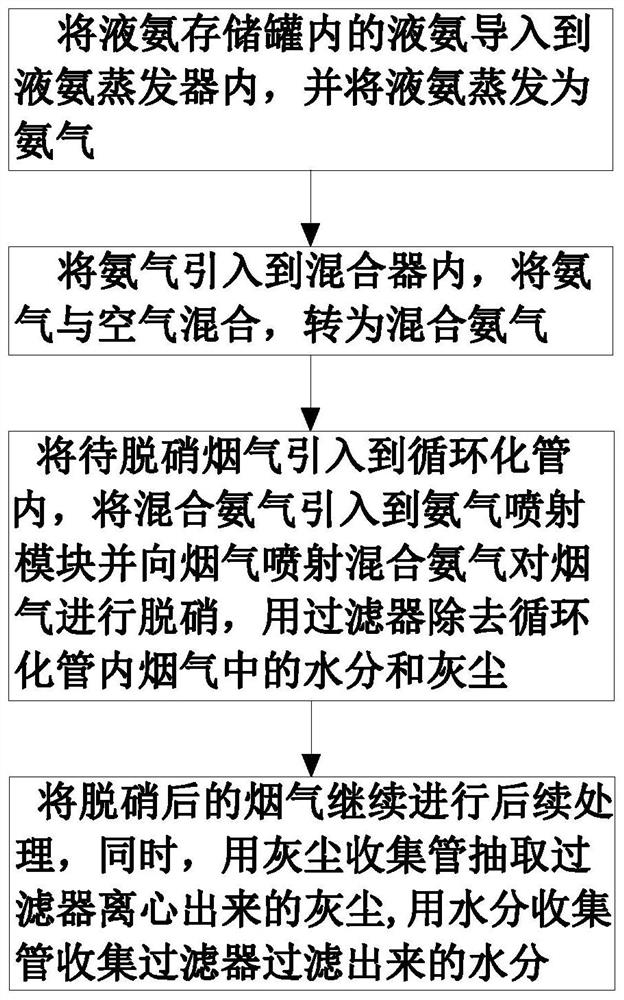
The invention belongs to the technical field of flue gas denitrification and particularly relates to an SCR industrial flue gas denitrification method. The denitrification method comprises the following steps: introducing liquid ammonia in a liquid ammonia storage tank into a liquid ammonia evaporator and evaporating the liquid ammonia into ammonia gas; introducing the ammonia gas into a mixer, mixing the ammonia gas with air and converting the ammonia gas into mixed ammonia gas; introducing the mixed ammonia gas into an SCR flue gas denitrification system, introducing the flue gas to be denitrified into the SCR flue gas denitrification system, denitrifying and dedusting the flue gas; continuously carrying out subsequent treatment of the denitrified and dedusted flue gas, and simultaneously collecting water and dust in the SCR flue gas denitrification system. Through the SCR industrial flue gas denitrification method, the flue gas is introduced into a plurality of sub circulation pipes, so that the contact time of the flue gas with the ammonia gas and the catalyst can be prolonged, and the contact area of the flue gas with the ammonia gas and the catalyst can be expanded; the improvement of the flue gas denitrification effect is facilitated; an ammonia gas injection die is used for injecting the mixed ammonia gas into the flue gas, so that the mixed ammonia gas is fully mixed with the flue gas, and the improvement of the flue gas denitrification efficiency is facilitated.

Description

technical field [0001] The invention belongs to the technical field of flue gas denitrification, in particular to a method for denitrification of SCR industrial flue gas. Background technique [0002] Flue gas denitrification refers to the reduction of generated NOX to N2, thereby removing NOX in flue gas. According to the treatment process, it can be divided into wet denitrification and dry denitrification. Since more than 90% of the NOx in the flue gas discharged from the combustion system is NO, and NO is difficult to dissolve in water, so the wet treatment of NOx cannot use a simple washing method. The principle of flue gas denitrification is to oxidize NO into NO2 with an oxidant, and then absorb the generated NO2 with water or alkaline solution to achieve denitrification. Selective catalytic reduction SCR denitrification is to use ammonia, CO or hydrocarbons as reducing agents in the presence of catalysts, and reduce NO in flue gas to N2 in the presence of oxygen. NH...

Claims


Application Information

Patent Timeline
Patent Type & Authority Patents(China)
IPC IPC(8): B01D53/90B01D53/56
CPCB01D53/8631B01D53/90B01D2251/2062B01D2258/0283
Inventor 朋仁锋
Owner 武汉凤凰绿色贸易有限公司
Learn More