Multi-channel quick detection micro-fluid detecting chip
A technology for detecting chips and microfluids, which is applied in laboratory appliances, laboratory containers, chemical instruments and methods, etc., can solve the problems of unreasonable inlet design, small detection flux, complex structure, etc., and achieve flow Fast, easy sample injection, and simple chip structure
- Summary
- Abstract
- Description
- Claims
- Application Information
AI Technical Summary
Problems solved by technology
Method used
Image
Examples
Embodiment 1
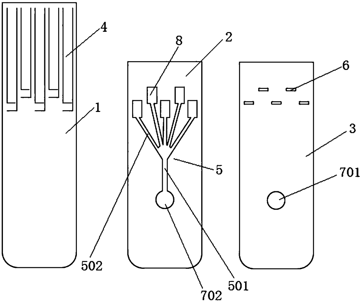
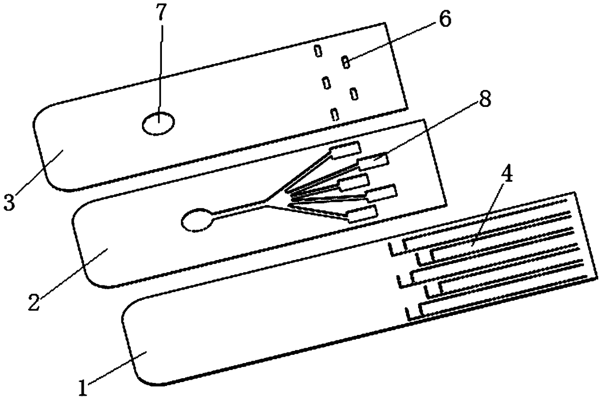
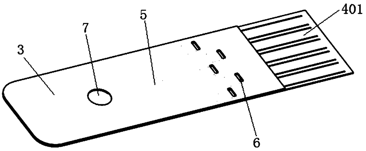
[0033] Embodiment 1: The multi-channel rapid detection microfluidic detection chip includes a chip body, and the chip body is provided with a chip sampling port 7, a plurality of mutually independent detection chambers 8 and microfluidic channels 5, and the chip sampling port 7 The micro-channel 5 communicates with the detection chamber 8, the chip body also includes an electrode 4, and the detection chamber 8 is connected to the electrode 4; the micro-channel 5 includes a main flow channel 501 and 5 branch channels. The microfluidic channel 502, the end of the main flow channel 501 is divided into five microfluidic channels 502, and the five microfluidic channels 502 communicate with the five independent detection chambers 8 one by one; the main flow The other end of the channel 501 communicates with the chip sampling port 7; the chip body sequentially includes a bottom layer 1, an intermediate layer 2 and an upper cover layer 3 from bottom to top, and the bottom layer 1, the ...
Embodiment 2
[0034] Embodiment 2: The difference from Embodiment 1 is that the structure of the chip sampling port 7 is different, and the bottom layer 1, the middle layer 2 and the upper cover layer 3 cooperate to define a closed microflow channel 5, a detection chamber 8 and a funnel Area 9; one side of the lower end of the bottom layer 1 is provided with a gap 10, and the liquid injection port 701, the funnel area 9 and the gap 10 are respectively arranged on the upper cover layer 3, the middle layer 2 and the corresponding bottom layer 1 The position and size are different; the chip sampling port 7 is composed of a liquid injection port 701, a funnel area 9 and a gap 10 and is connected to the bottom of the detection chamber 8 through the micro flow channel 5; specifically: the multiple The channel rapid detection microfluidic detection chip includes a chip body, and the chip body is provided with a chip sampling port 7, a plurality of mutually independent detection chambers 8 and a mic...
Embodiment 3
[0035]Embodiment 3: The difference from Embodiment 1 is that the structure of the chip sampling port is different, and the bottom plate layer 1, the middle layer 2 and the upper cover layer 3 cooperate to define a closed micro flow channel 5, a detection chamber 8 and a funnel area 9. A notch 10 is provided on one side of the lower end of the bottom layer 1, and the liquid injection port 701, the funnel area 9 and the notch 10 are respectively arranged at corresponding positions on the upper cover layer 3, the middle layer 2 and the bottom layer 1 and different sizes; the chip sampling port 7 is composed of a liquid injection port 701, a funnel region 9 and a gap 10 and is connected to the bottom of the detection chamber 8 through the micro-channel 5; specifically: the multi-channel The rapid detection microfluidic detection chip includes a chip body, and the chip body is provided with a chip sampling port 7, a plurality of mutually independent detection chambers 8 and micro fl...
PUM
 Abstract
Description
Claims
Application Information
 - R&D
- Intellectual Property
- Life Sciences
- Materials
- Tech Scout
- Unparalleled Data Quality
- Higher Quality Content
- 60% Fewer Hallucinations
Browse by: Latest US Patents, China's latest patents, Technical Efficacy Thesaurus, Application Domain, Technology Topic, Popular Technical Reports.
© 2025 PatSnap. All rights reserved.Legal|Privacy policy|Modern Slavery Act Transparency Statement|Sitemap|About US| Contact US: help@patsnap.com


