
Special scroll machining machine tool and machining method thereof

A special machine tool and scroll technology, which is applied in metal processing machinery parts, metal processing equipment, manufacturing tools, etc., can solve the problems of processing noodle-shaped defects, complex helical shape, and reduce processing accuracy, and achieve accurate movement and improve production. The effect of precision and improved stability

Pending Publication Date: 2018-11-06
ZHEJIANG DEREBAO ELECTRIC TECH
View PDF0 Cites 5 Cited by
  • Summary
  • Abstract
  • Description
  • Claims
  • Application Information

AI Technical Summary

Problems solved by technology

Due to the complex shape of the helical surface of the vortex, the error generated by this processing method when passing the quadrant can easily cause strip defects on the processed surface, so follow-up inspection and finishing are required to make up for the processing defects and meet the use requirements.
In addition, due to the limitation of the processing method, most of the current scroll processing machine tools need more parts to achieve spiral trajectory processing, which makes the main shaft overhang large and the force is unstable. It is necessary to add overhang deviation compensation, thereby reducing the machining accuracy.

Method used


Image

  • Special scroll machining machine tool and machining method thereof
  • Special scroll machining machine tool and machining method thereof
  • Special scroll machining machine tool and machining method thereof

Examples


Embodiment Construction

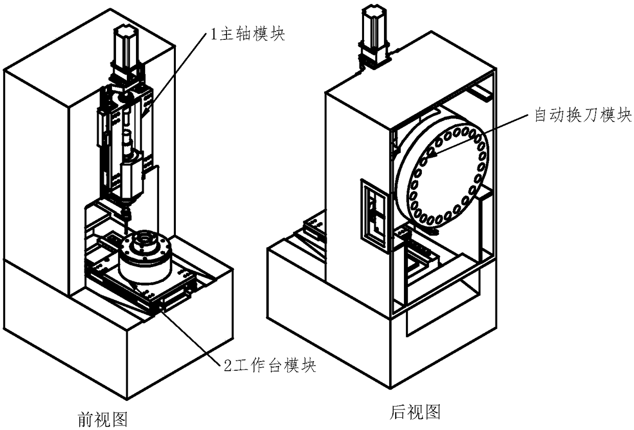
[0040] The special machine tool of the present invention is composed of a spindle module 1 , a workbench module 2 , an automatic tool change module 3 and a lubricating and cooling system 4 .

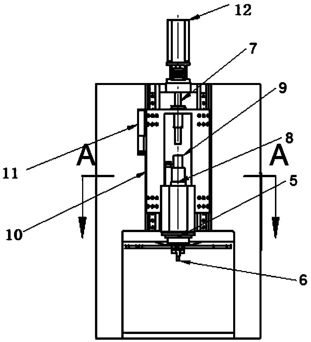
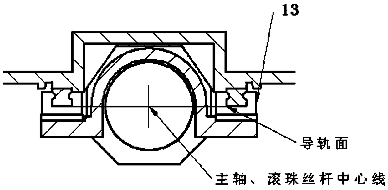
[0041] Among them, the spindle module such as figure 2 and image 3 As shown; the main shaft adopts the electric main shaft 5, configures the rotary water inlet 9 to realize the central water outlet function, and configures the knife cylinder 8 to realize the function of cutting and loading when the tool is changed automatically; the milling cutter 6 is installed on the head of the main shaft and adopts the HSK50E knife The handle structure is connected; the Z-axis slide table 10 has the main shaft installation hole coaxial with the ball screw pair 7 installation holes, and the screw transmission force is coaxial with the main shaft force, which improves the stability of the slide table movement; the Z-axis slide table 10 has the main shaft The center line of the installation hole and ...


PUM


Abstract

The invention discloses a special scroll machining machine tool and a machining method thereof. The special scroll machining machine tool comprises a base, a spindle module, a workbench module, an automatic tool changing module and a cooling lubrication module, wherein the spindle module, the workbench module, the automatic tool changing module and the cooling lubrication module are arranged on the base. The machining movement mechanism of the special scroll machining machine tool is that an electric spindle drives a tool to rotate at a high speed, tool cutting-in feed is achieved through Z-axis servo, a workbench DD motor drives a workpiece to do rotary motion, workpiece radial feed movement is achieved through X-axis servo feed of the workbench DD motor, a polar coordinate motion interpolation track is achieved through the combination of the above two motions, and the mode is the optimal movement mode for scroll spiral line machining; a film hydraulic operated clamp or a film pneumatic clamp is used for workpiece clamping, and high-precision clamping and positioning are achieved; and the high precision and high efficiency requirements for scroll plate machining are achieved through the special scroll machining machine tool and the machining method thereof.

Description

technical field [0001] The invention relates to a special machine tool for scroll processing and a processing method thereof, in particular to the processing of thin-walled spiral scrolls in scroll compressors. Background technique [0002] A scroll compressor is a volumetric compression compressor, and the compression components are composed of a moving scroll and a static scroll. A number of structural features are included to allow for a shunt flow of gas through the compressor casing to reduce oil entrainment. [0003] After entering the casing, some of the gas flows upward to reduce the amount of gas flowing downward towards the oil. To achieve this, the motor of the compressor may be surrounded by a sleeve having upper and lower holes for directing air flow to the upper and lower stator end turns of the motor. In some embodiments, it is important to position the suction inlet relative to the two gas passages between the stator and the motor housing. The inlet is pos...

Claims


Application Information

Patent Timeline
IPC IPC(8): B23Q1/48B23Q3/08B23Q3/157B23Q5/36B23Q11/00B23Q11/10B23Q11/12
CPCB23Q1/48B23Q3/08B23Q3/082B23Q3/15706B23Q5/36B23Q11/0042B23Q11/10B23Q11/12
Inventor 唐安伟余志军施桂和王猛杨春炜陈坤见王虎
Owner ZHEJIANG DEREBAO ELECTRIC TECH
Learn More