Oil and cutting fluid separation device of cutting fluid purifier

A technology of oil-liquid separation and cutting fluid, which is applied in the fields of chemistry, metal processing machinery parts, maintenance and safety accessories, etc. It can solve the problems of shortening the service life, accelerating the aging and deterioration of cutting fluid, reducing the performance of cutting fluid, etc., and prolonging the use Life expectancy, reduction of pollution and waste discharge, and the effect of reducing enterprise costs

Active Publication Date: 2018-11-06
逸乐(廊坊)环保科技有限公司
View PDF6 Cites 0 Cited by
  • Summary
  • Abstract
  • Description
  • Claims
  • Application Information

AI Technical Summary

Problems solved by technology

[0004] The cutting fluid purifier of the machine tool is used to purify the cutting fluid. The cutting fluid purification equipment currently used is mostly centrifugal structure, the processing speed is slow, the purification is not complete, the maintenance method is cumbersome, time-consuming and laborious, and the residue is collected using non-woven bags. Filtering is easy to block, and the cloth bag is a one-time consumable, which is also a pollutant. Long-term use will generate a large amount of polluting garbage, which will not achieve environmental protection and increase the cost of use; the lack of recognition performance of waste oil and cutting fluid will cause oil The liquid separation is not complete, and the oil-liquid mixture will reduce the performance of the cutting fluid, affecting the service life of the tool and the machining accuracy of the machine parts
As far as the current purification equipment does not have a sterilizing device, as the cutting fluid is used for a long time, the multiplication of bacteria will accelerate the aging and deterioration of the cutting fluid, shorten the service life, and cannot achieve the purpose of reducing pollution and reducing costs

Method used


Image

  • Oil and cutting fluid separation device of cutting fluid purifier

Examples


Embodiment Construction

[0021] The present invention will be further described in detail below in conjunction with the accompanying drawings and specific embodiments.

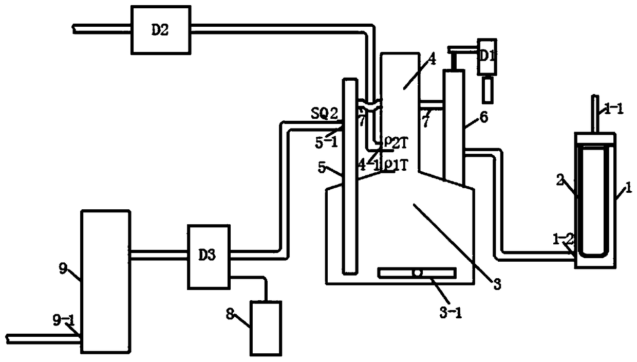
[0022] Depend on figure 1 As can be seen from the shown embodiment, the present embodiment includes a filter device, an oil-liquid separation device and an ozone sterilizing treatment device, the filter device includes a filter container 1, the upper end of the filter container 1 is provided with a liquid inlet 1-1, and the lower end of the filter container 1 There is a liquid discharge port 1-2, and a filter screen 2 is provided between the filter container 1 and the liquid discharge port 1-2. The oil-liquid separation device includes a sedimentation chamber 3, a waste oil collection chamber 4, a negative pressure generating device and a cutting fluid The separation pipe 5, the negative pressure generating device includes a negative pressure pump D1 and a negative pressure pipe 6 connected with the negative pressure pump D1 to genera...


PUM


Abstract

The invention discloses an oil and cutting fluid separation device of a cutting fluid purifier. The oil and cutting fluid separation device comprises a sedimentation chamber, a waste oil collection chamber, a negative pressure generating device and a cutting fluid separation tube; the negative pressure generating device comprises a negative pressure pump D1 and a negative pressure tube; the wasteoil collection chamber is arranged above the center of the top of the sedimentation chamber; a waste oil discharging opening is formed in the waste oil collection chamber, a first fluid density sensorrho1T is arranged at the bottom of the waste oil collection chamber, a second fluid density sensor rho2T is arranged at the lower edge of the waste oil discharging opening, the bottom of the waste oil discharging opening communicates with the position, close to the bottom of the sedimentation chamber, of the interior of the sedimentation chamber, and the cutting fluid separation tube and the waste oil collection chamber communicates with the upper part of the negative pressure tube through a communicating tube; and a cutting fluid discharging opening is formed in the cutting fluid separationtube, and a cutting fluid level switch SQ2 is arranged above the position close to the top of the cutting fluid discharging opening. By means of the oil and cutting fluid separation device, cutting fluid of a machining machine tool can be purified and sterilized well so as to prolong the service life of the cutting fluid.

Description

[0001] This application is a divisional application with the application number 201810252437.2, the application date is March 26, 2018, and the title of the invention is "a cutting fluid purifier for machining machine tools and its use method". technical field [0002] The invention relates to the technical field of machining machine tools. Background technique [0003] Machining machine tools need to use cutting fluid during the processing of machine parts. The cutting fluid is recycled through the cutting fluid circulation system of the machine tool. With the extension of the cycle time, impurities will be generated in the cutting fluid. The impurities are mainly metal chips and waste. Oil (machine tool lubricating oil) composition. [0004] The cutting fluid purifier of the machine tool is used to purify the cutting fluid. The cutting fluid purification equipment currently used is mostly centrifugal structure, the processing speed is slow, the purification is not complete...

Claims


Application Information

Patent Timeline
Patent Type & Authority Applications(China)
IPC IPC(8): B23Q11/00B23Q11/10A61L2/20
CPCA61L2/202B23Q11/00B23Q11/1069
Inventor 杨俊学张敬爽苏艳杰程磊刘一飞王丹史昊天丰志良王成龙
Owner 逸乐(廊坊)环保科技有限公司
Why Eureka
Try Eureka