Cooling device for blow-molded plastic barrel of blow-molding machine

A technology of a cooling device and a plastic barrel, which is applied in the field of cooling devices for blow molding plastic barrels by blow molding machines, can solve the problem that the cooling effect is difficult to guarantee, the labor intensity of online operators is high, and the blow molding efficiency of the blow molding machine is affected. problem, to achieve the effect of good automation, saving labor resources, and excellent cooling efficiency

Pending Publication Date: 2018-11-06
SUZHOU TONGDA MACHINERY
View PDF1 Cites 6 Cited by
  • Summary
  • Abstract
  • Description
  • Claims
  • Application Information

AI Technical Summary

Problems solved by technology

In the past, stochastic cooling was usually used for cooling large-capacity plastic barrels, that is, cooling in the mold of the blow molding machine. This cooling method is performed under the control of the mold, so the plastic barrels are less likely to be deformed, but due to random It takes a long time to cool down with the mold, which affects the blow molding efficiency of the blow molding machine
The natural cooling method after the mold is released has relatively little impact on the blow molding efficiency of the blow molding machine, but the plastic barrel is prone to deformation during the cooling process, and in severe cases it will be scrapped
[0003] In the published Chinese patent literature, it can be seen that the technical information on blow molding plastic barrels blown by blow molding machines is cooled by compressed air, typically such as CN205058424U recommending "a cooling device for plastic barrels", although this patent solution is to a certain extent However, by reading the full text of the patent specification, it is not difficult to find

Method used


Image

  • Cooling device for blow-molded plastic barrel of blow-molding machine
  • Cooling device for blow-molded plastic barrel of blow-molding machine
  • Cooling device for blow-molded plastic barrel of blow-molding machine

Examples


Embodiment Construction

[0024] In order to understand the technical essence and beneficial effects of the present invention more clearly, the applicant will describe in detail the following examples, but the descriptions of the examples are not intended to limit the solutions of the present invention. Equivalent transformations that are only formal but not substantive should be regarded as the scope of the technical solution of the present invention.

[0025] In the following descriptions, all the concepts related to the directions or azimuths of up, down, left, right, front and back are aimed at the position state of the picture being described, so they cannot be understood as Special limitations on the technical solutions provided by the invention.

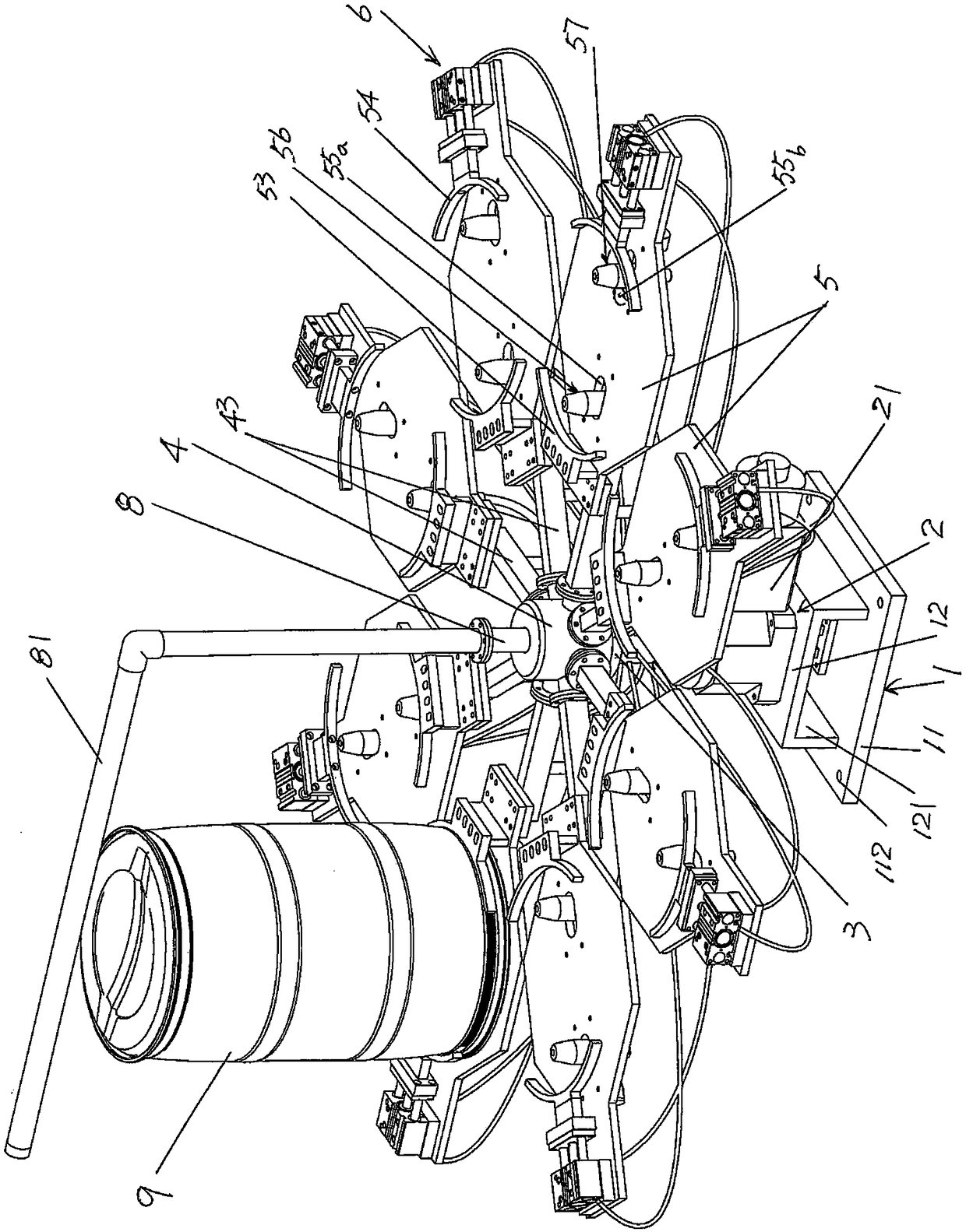
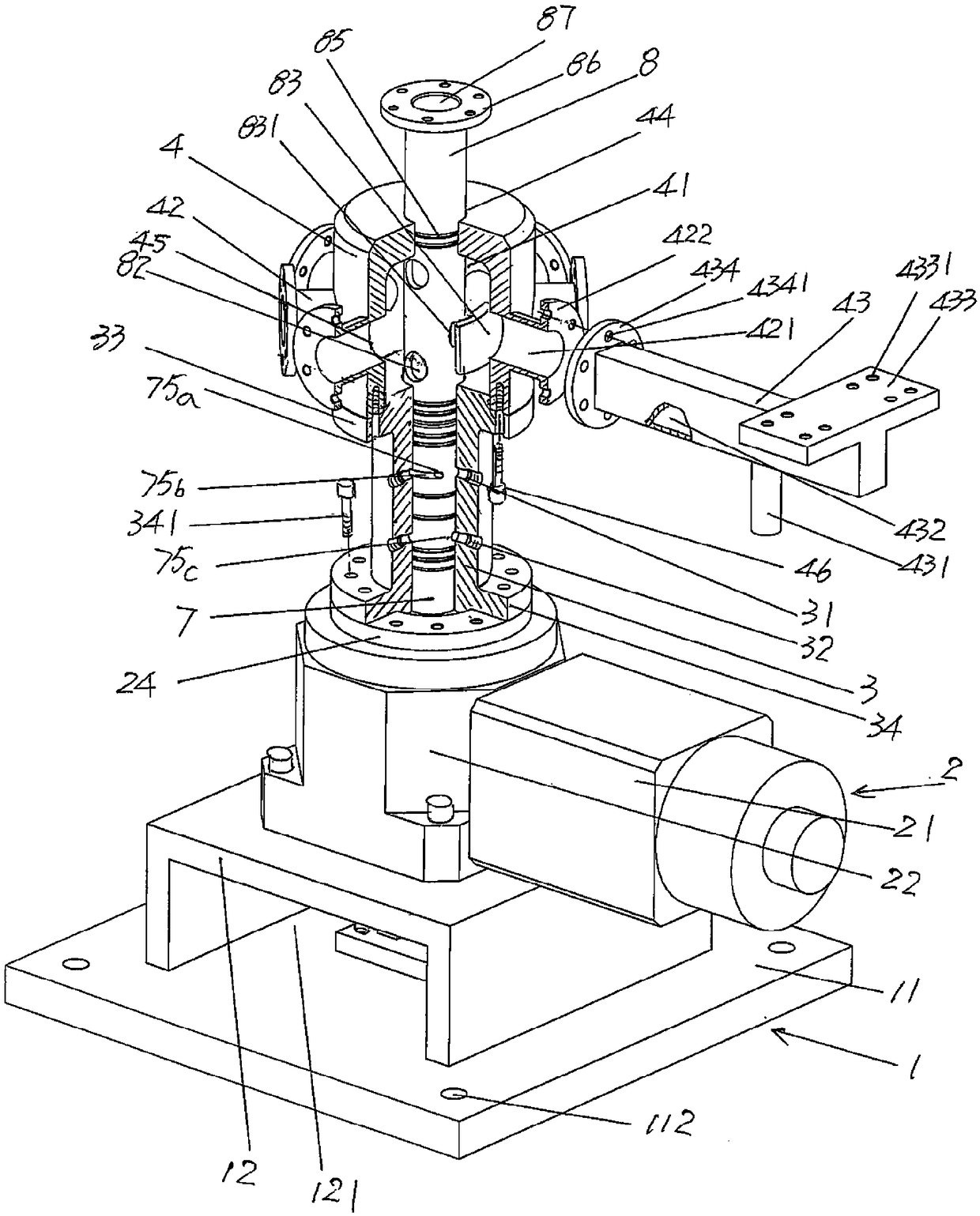
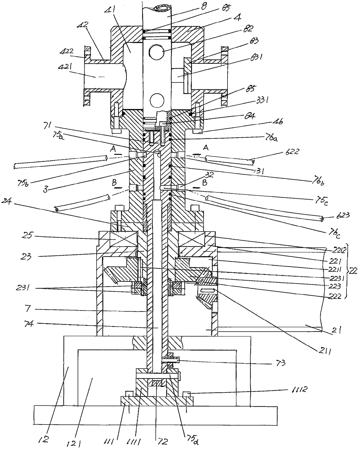
[0026] See figure 1 and image 3 , shows the support mechanism 1, the support mechanism 1 is directly or indirectly set on the floor in the state of use (will be described later); shows an air supply rotary seat drive mechanism 2, the air supply rota...


PUM


Abstract

The invention discloses a cooling device for a blow-molded plastic barrel of a blow-molding machine. The cooling device comprises a supporting mechanism, a gas supply rotary base drive mechanism whichis arranged on the supporting mechanism, a gas supply rotary base which is connected with the gas supply rotary base drive mechanism, a rotary arm fixed base which is fixed with the gas supply rotarybase, a rotary cooling platform, a central gas supply tube and an upper shaft column, wherein a platform rotary arm fixed interface is arranged on the outer wall of the rotary arm fixed base; a platform rotary arm is arranged on the platform rotary arm fixed interface; the lower part of the platform rotary arm is equipped with a platform rotary arm gas tube connecting nozzle; a plastic barrel static clip is arranged on the rotary cooling platform; a plastic barrel movable clip drive mechanism is arranged on the horizontal cantilever end of the rotary cooling platform; a gas spraying mechanismand a gas return mechanism are arranged on the middle part of the rotary cooling platform; the upper end of the central gas supply tube is positioned in the gas supply rotary base, and the lower endof the central gas supply tube is fixed with a supporting mechanism; and the upper end of the upper shaft column is connected to a cooling gas lead-in tube, the lower end of the upper shaft column isfixed with the upper part of the central gas supply tube, and the middle part of the upper shaft column is positioned in the rotary arm fixed base. The cooling device relieves online operating strength, ensures cooling effect and efficiency, prevents thermal radiation from harming a body, and is good in automatic effect.

Description

technical field [0001] The invention belongs to the technical field of cooling facilities, and in particular relates to a cooling device for blow molding plastic barrels by a blow molding machine. Background technique [0002] The blow-molded plastic barrels mentioned above mainly refer to plastic barrels with a relatively large volume such as 200L or more. Such large-volume or large-capacity plastic barrels need to be cooled after blowing. In the past, stochastic cooling was usually used for cooling large-capacity plastic barrels, that is, cooling in the mold of the blow molding machine. This cooling method is performed under the control of the mold, so the plastic barrels are less likely to be deformed, but due to random It takes a long time to cool down with the mold, which affects the blow molding efficiency of the blow molding machine. The natural cooling method after the mold is released has relatively little impact on the blow molding efficiency of the blow molding m...

Claims


Application Information

Patent Timeline
IPC IPC(8): B29C49/64B29L22/00
CPCB29C49/64B29L2031/7154
Inventor 肖志林杨晓东陈华庞阳肖玮祺卫锦尧
Owner SUZHOU TONGDA MACHINERY
Why Eureka
Try Eureka