Biomass particle catalytic device

A technology of biomass particles and equipment, which is applied in the direction of mold extrusion granulation, biofuel, chemical/physical/physicochemical processes, etc. It can solve problems such as inability to place catalytic devices, affect factory production efficiency, and reduce carbon dioxide emissions. Achieve the effect of reducing the volume of equipment, increasing the catalytic speed and improving production efficiency

Inactive Publication Date: 2018-11-06
MENGCHENG SHENGYAN STRAW
View PDF10 Cites 1 Cited by
  • Summary
  • Abstract
  • Description
  • Claims
  • Application Information

AI Technical Summary

Problems solved by technology

[0003] my country is a country with a large energy consumption. It is an inevitable choice to adjust the energy structure and use biomass energy. The use of biomass particles mainly has the following functions: replacing coal, thereby reducing primary energy consumption, realizing carbon cycle, reducing greenhouse gas carbon dioxide emissions, and increasing agricultural production. Added value, increase farmers' income, conform to national industrial policy, have far-reaching significance such as good economic and social benefits, the existing biomass particles need to be produced after the raw materials pass through the catalytic equipment, and the volume of the existing catalytic equipment on the market It is larger and needs to occupy a larger space, making it impossible to place more catalytic devices in the factory, which affects the production efficiency of the factory

Method used


Image

  • Biomass particle catalytic device
  • Biomass particle catalytic device
  • Biomass particle catalytic device

Examples


Embodiment Construction

[0024] The following will clearly and completely describe the technical solutions in the embodiments of the present invention with reference to the accompanying drawings in the embodiments of the present invention. Obviously, the described embodiments are only some, not all, embodiments of the present invention. Based on the embodiments of the present invention, all other embodiments obtained by persons of ordinary skill in the art without making creative efforts belong to the protection scope of the present invention.

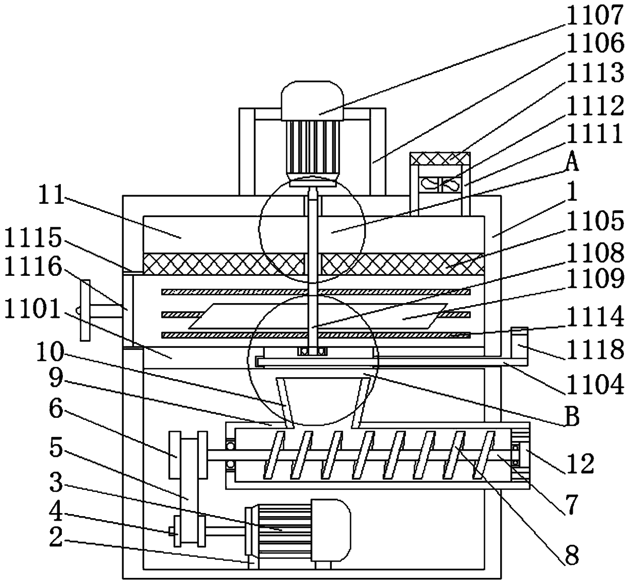
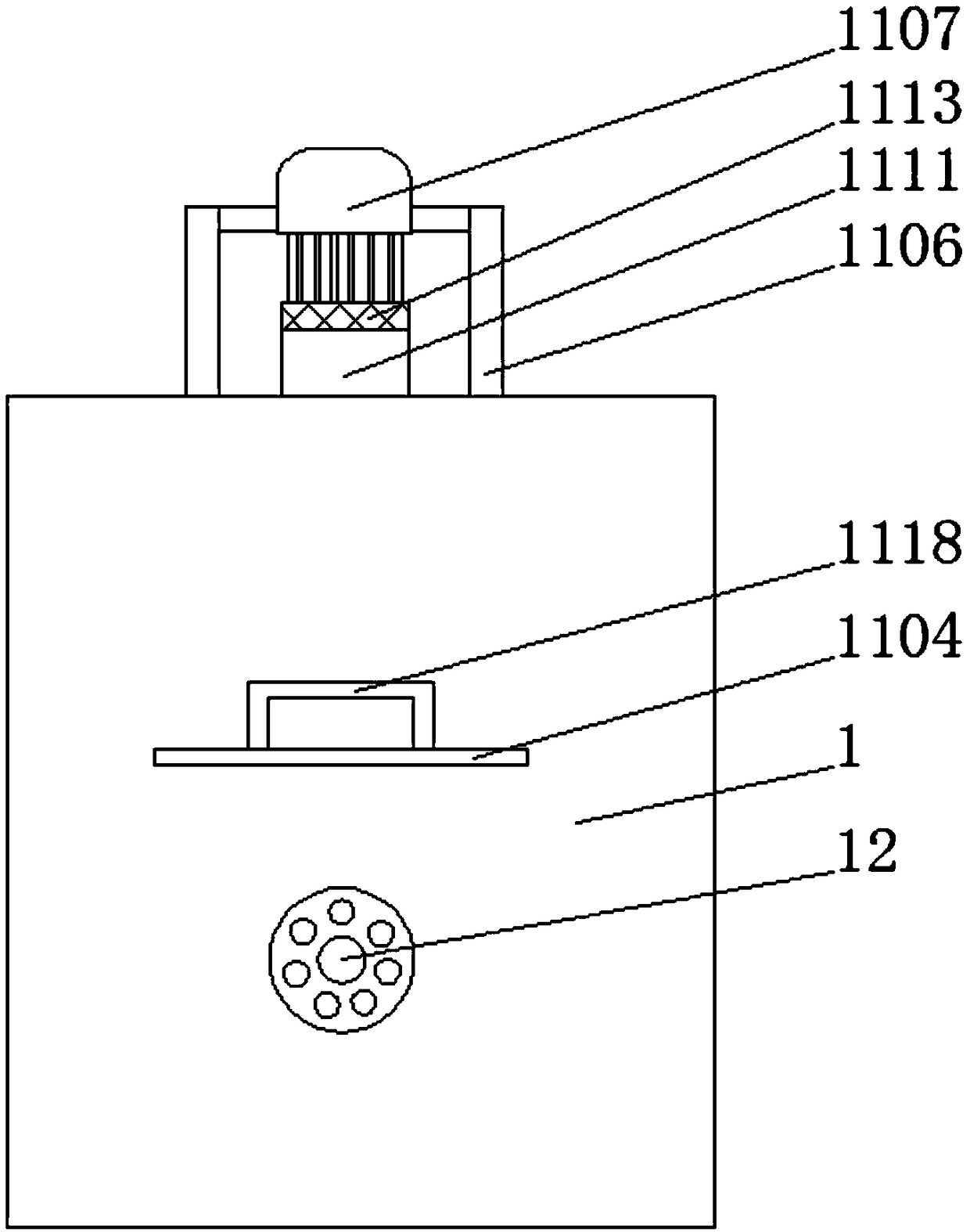
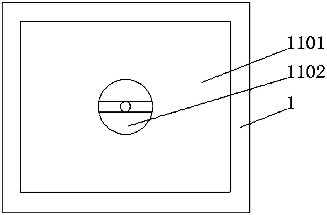
[0025] see Figure 1-5 , the present invention provides a technical solution: a kind of biomass particle catalytic equipment, including the equipment casing 1, the bottom of the inner cavity of the equipment casing 1 is fixedly connected with the compression motor frame 2, and the top of the compression motor frame 2 is fixedly connected with the compression motor 3. The output end of the compression motor 3 is fixedly connected with the first transmission pul...


PUM


Abstract

The invention discloses a biomass particle catalytic device. The device comprises a device casing. The bottom of an inner cavity of the device casing is fixedly connected with a compression motor frame, and a compression motor is fixedly connected to the top of the compression motor frame, the output end of the compression motor is fixedly connected with a first transmission pulley, the surface ofthe first transmission pulley is in transmission connection with a transmission belt, the first transmission pulley is connected with a second transmission pulley through the transmission belt, one side of the second transmission pulley is fixedly connected with an extrusion rotating shaft, the upper half portion of the inner cavity of the device casing is provided with a catalytic chamber. Due to the fact that the upper half portion of the inner cavity of the device casing is provided with the catalytic chamber, catalyzed raw materials can be directly introduced into a feeding funnel througha feeding hole after catalysis of the raw materials, the device size is reduced, more catalytic devices can be placed on the same area, and the production efficiency is improved.

Description

technical field [0001] The invention relates to the technical field of agricultural machinery, in particular to biomass particle catalytic equipment. Background technique [0002] The research and development of bioenergy technology has become one of the world's major hot topics, and has attracted the attention of governments and scientists around the world. Many countries have formulated corresponding development and research plans, such as the Sunshine Project in Japan, the Green Energy Project in India, and the Energy Farm in the United States, among which the development and utilization of bioenergy occupies a considerable share. Many foreign bioenergy technologies and devices have reached the level of commercial application. Compared with other biomass energy technologies, biomass pellet fuel technology is easier to achieve large-scale production and use. The convenience of using bioenergy particles is comparable to energy such as gas and oil. Taking the United States...

Claims


Application Information

Patent Timeline
Patent Type & Authority Applications(China)
IPC IPC(8): C10L5/44B01J19/18B01J2/22
CPCB01J2/22B01J19/0066B01J19/18B01J2219/00135C10L5/44C10L5/442C10L5/445C10L2290/32Y02E50/10Y02E50/30
Inventor 孟永徐兴振
Owner MENGCHENG SHENGYAN STRAW
Why Eureka
Try Eureka