Photovoltaic pavement system

A photovoltaic and pavement technology, applied to roads, roads, pavement details, etc., can solve the problems of base layer damage, easy water permeability, poor flatness, etc., and achieve the effects of avoiding deformation and damage, uniform heating area, and good ventilation performance

Active Publication Date: 2018-11-06
榛硕(武汉)智能科技有限公司
View PDF7 Cites 8 Cited by
  • Summary
  • Abstract
  • Description
  • Claims
  • Application Information

AI Technical Summary

Problems solved by technology

[0006] The above-mentioned four types of solar photovoltaic power generation pavement technologies are still in the conceptual and experimental stage, and there are many major defects in the pavement structure that do not meet the basic requirements of road engineering. The base layer was destroyed, which led to problems such as excessive deformation of the surface layer; the cement concrete prefabrication technology in the Netherlands faced difficulties such as on-site assembly of large components and insufficient anti-skid ability of the tempered glass on the surface, so only small-scale tests were carried out on bicycle lanes; The buried technology lacks protection for the photovoltaic panel power generation layer, and it is very easy to damage the photovoltaic power generation layer under the action of vehicle loads, which eventually leads to the loss of power generation capacity of the road surface; although the photovoltaic experimental road section opened in Jinan, Shandong Province can carry small cars and medium-sized trucks And melt the snow on the road, but the hot weather can not cool the road, which leads to a greatly shortened service life of photovoltaic roads

Method used


Image

  • Photovoltaic pavement system
  • Photovoltaic pavement system
  • Photovoltaic pavement system

Examples


Embodiment 1

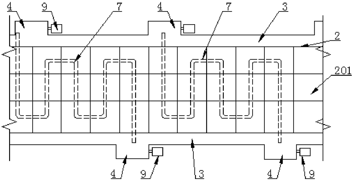
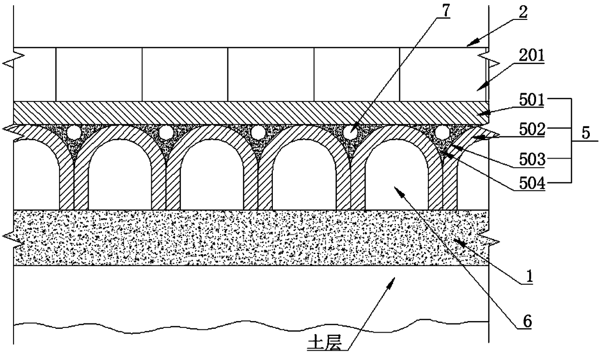
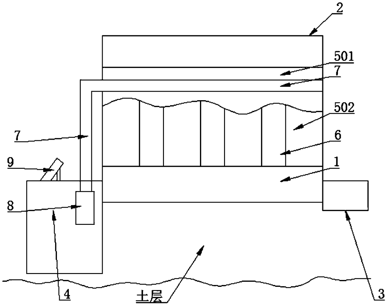
[0035] Such as Figure 1-3 As shown, a photovoltaic pavement system includes a master control unit, a subgrade 1, a photovoltaic pavement 2, and drainage grooves 3 on both sides of the photovoltaic pavement 2. The photovoltaic pavement 2 is composed of several photovoltaic panel modules 201 arranged in a row. 3 Water collection pools 4 are arranged at intervals; a support part 5 is provided on the roadbed 1, and a water collection channel 6 is formed between the roadbed 1 and the support part 5; the photovoltaic panel module 201 is laid on the support part 5 A circulating water pipe 7 is provided between the photovoltaic panel module 201 and the support part 5, and a heat collector 9 is provided at the sump 4, and the circulating water pipe 7 passes through the first water pump 8 and the heat collector 9 connected.

[0036] When the present invention is in use, the load brought by the vehicle running on the photovoltaic road surface 2 is directly transmitted to the photovolta...

Embodiment 2

[0040] Such as Figure 4 As shown, a photovoltaic pavement system. The structure and principle of this embodiment are similar to those of Embodiment 1. The difference between this embodiment and Embodiment 1 is that the photovoltaic panel module 201 sequentially includes a tempered glass layer 2011, Photovoltaic panel 2012, substrate 2013, an insulating buffer layer 2014 is provided above the substrate 2013, a boss 20131 is provided on the substrate 2013, and the boss 20131 passes through the insulating buffer layer 2014, photovoltaic panel 2012 and tempered The glass layers 2011 are bonded together. Firstly, the insulating buffer layer 2014 not only has a certain buffering effect on the load transmitted by the tempered glass layer 2011, but also prevents the electric energy on the photovoltaic panel 2012 from being transmitted to the support portion 5, reducing the occurrence of safety accidents.

Embodiment 3

[0042] Such as Figure 5 As shown, a photovoltaic pavement system. The structure and principle of this embodiment are similar to those of Embodiment 1 and Embodiment 2. The difference between this embodiment and Embodiment 1 and Embodiment 2 is that the arch support 502 is provided with A water level sensor 11, the water level sensor 11 is electrically connected with the master control unit.

[0043] The sump 4 is provided with a second water pump 12, and the second water pump 12 is electrically connected to the master control unit.

[0044] The water in the water collecting channel 6 not only has the effect of cooling, but also has a certain supporting effect. A water level sensor 11 is set on the arch support 502, and the water level sensor 11 is electrically connected with the master control unit. The water in the water collecting channel 6 is used to support the photovoltaic pavement 2 within a certain water level. When the water level in the water collecting channel 6 is...


PUM


Abstract

The invention discloses a photovoltaic pavement system. The photovoltaic pavement system comprises a general control unit, a roadbed, a photovoltaic pavement and drainage troughs on both sides of thephotovoltaic pavement. The photovoltaic pavement comprises a plurality of photovoltaic panel modules. The photovoltaic pavement system is characterized in that the roadbed is provided with a support part, the support part is used for supporting the photovoltaic module, a water collecting channel is formed between the roadbed and the support part, a water collecting tank is provided with water collection tanks at intervals, the support part is paved with the photovoltaic panel modules, a circulating water pipe is disposed between the photovoltaic panel module and the support part, a heat collector is arranged at the water collecting tank, and the circulating water pipe is communicated with the heat collector through a first water pump. The photovoltaic pavement system realizes cooling of the photovoltaic pavement in the hot weather, and melting of the snow and the ice layer on the photovoltaic pavement in the cold weather. The support part transforms the bending moment stress generatedby the load on the photovoltaic panel module into compressive stress or transforms the most of the bending moment stress into compressive stress and prolongs the service life of the photovoltaic panelmodule and the service life of the whole photovoltaic pavement.

Description

technical field [0001] The invention relates to traffic pavements, in particular to a photovoltaic pavement system, which is mainly applicable to the pavement application of expressways. Background technique [0002] The concept of photovoltaic roads first appeared in 2006. In 2013, the Bruces of Idaho, USA, developed a hexagonal solar slab shaped like a brick with a concave-convex surface. On a cement concrete base. In addition to its unproven load-carrying and road performance, this structure is expensive and requires a lot of labor. Therefore, so far, only a 15-square-meter open-air structure has been built in Sandpoint, Idaho, USA. PARKING LOT. [0003] In November 2014, a 230-foot-long (about 70 meters) solar bicycle road was officially opened in a town called Cromeny in the Netherlands. The road is made of 2.4m x 3.3m prefabricated cement concrete slabs, and the solar cells are placed under layers of tempered glass. [0004] The French company COLAS used the direct...

Claims


Application Information

Patent Timeline
Patent Type & Authority Applications(China)
IPC IPC(8): E01C9/00E01C3/00E01C11/22E01C11/24E01C11/26
CPCE01C3/00E01C9/00E01C11/225E01C11/227E01C11/24E01C11/265
Inventor 刘双
Owner 榛硕(武汉)智能科技有限公司
Why Eureka
Try Eureka