Laser radar

A technology of laser radar and laser emission system, applied in the direction of electromagnetic wave re-radiation, utilization of re-radiation, measurement device, etc., can solve the problems of low production efficiency, complex process, shortening the service life of detectors, etc.

Pending Publication Date: 2018-11-06
HESAI TECH CO LTD
View PDF6 Cites 23 Cited by
  • Summary
  • Abstract
  • Description
  • Claims
  • Application Information

AI Technical Summary

Problems solved by technology

Conventionally used semiconductor laser pulse diodes have a very small light-emitting area, but in fact, due to the influence of the chip package and the size of the driving circuit, the distance between the lasers cannot become very dense.
Considering this practical limitation, in order to achieve a higher number of lines and a higher angular resolution, it is forced to increase the density of angles and the number of lines by adding more columns of lasers in the horizontal direction, which will lead to The more columns, the more difficult the production and adjustment, the more complex the process, and the lower the production efficiency; the space utilization rate in the system is low, the focal plane position is particularly crowded, the heat generation is large, and the heat is difficult to be ex

Method used


Image

  • Laser radar
  • Laser radar
  • Laser radar

Examples


Embodiment 1

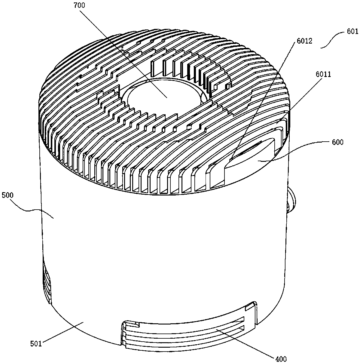
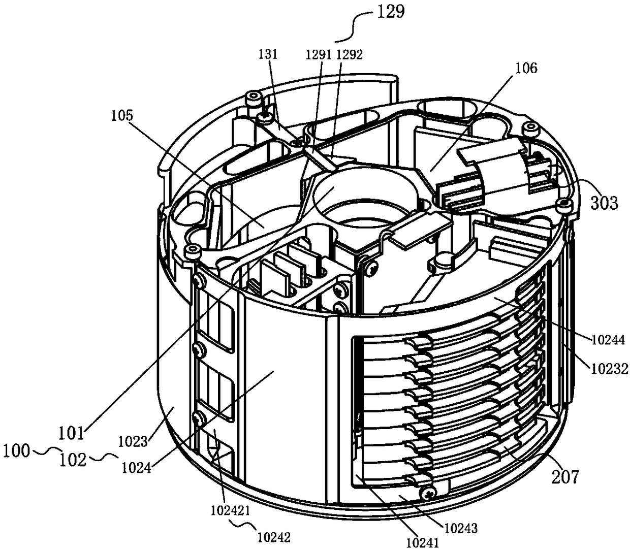
[0215] to combine figure 2 , image 3 , Figure 30 and Figure 31 As shown, a laser radar includes a rotor 100, a laser emitting system 200, and a receiving system 300. The rotor 100 has a mutually isolated launching cabin 105 and a receiving cabin 106, and the laser emitting system 200 is arranged in the launching cabin 105. In, the receiving system 300 is arranged in the receiving cabin 106,

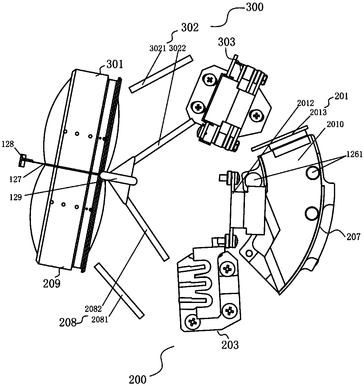
[0216] The laser emitting system 200 includes a transmitting circuit group 201, a first number of outgoing optical fibers 202 and an optical fiber fixing device 203; the transmitting circuit group 201 includes a second number of laser light sources, and the laser beam emitted by the laser light source is coupled to The outgoing optical fiber 202;

[0217] The fiber fixing device 203 includes three fiber fixing plates 204, the fiber fixing plate 204 has opposite first side 2041 and second side 2042, and at least one fiber fixing groove 2043 is opened on the first side 2041, so The...

Embodiment 2

[0332] Such as Figure 32 As shown, the difference between this embodiment and Embodiment 1 is that the fixed base includes a first fixed base 205, and the first fixed base 205 is fixed on the second bottom plate 103 of the rotor 100. The first fixing base 205 includes a first base plate 2051 , the top surface of the first base plate 2051 is provided with a first fixing structure for installing the fiber fixing plate 204 . The first fixing structure includes a first groove 2052, the first groove 2052 is opened on the top surface of the first fixing base 205, and the optical fiber fixing plate 204 is installed in the first groove 2052 ; The first groove 2052 is provided with spacers for separating adjacent fiber fixing plates 204, and the number of spacers is 2. One end of the optical fiber fixing plate 204 is placed in the first groove 2052, and the optical fiber fixing plate 204 and the first substrate 2051 are fixed by bonding. In addition, the optical fiber fixing plate 20...

Embodiment 3

[0334] Such as Figure 33 As shown, the difference between this embodiment and Embodiment 1 is that the fixed base includes a second fixed base 206, the second fixed base 206 is fixed on the side wall 603 of the rotor 100, and the first The two fixed bases 206 include a second base plate 2061 and a first side plate 2062, the first side plate 2062 is connected to the second base plate 2061, and the first side plate 2062 is provided with a fixing plate for installing the optical fiber 204 of the second fixed structure. The second fixed base 206 is T-shaped, the second base plate 2061 is attached to the side wall 603 of the rotor 100, the second base plate 2061 is connected to the rotor 100 through a connecting piece, and the first The side panels 2062 are parallel to the horizontal plane. The second fixing structure includes three second grooves 2063 , the second grooves 2063 correspond to the fiber fixing plates 204 one by one, and the fiber fixing plates 204 are connected to...


PUM


Abstract

The invention provides a laser radar. The laser radar comprises a rotor, a laser emitting system and a receiving system; the rotor is provided with an emitting cabin and a receiving cabin which are separated from each other; the laser emitting system is arranged in the emitting cabin; the receiving system is arranged in the receiving cabin; the laser emitting system comprises an emitting circuit group, a first number of outgoing optical fibers, and an optical fiber fixing device; the emitting circuit group includes a second number of laser light sources; laser beams emitted by the laser lightsources are coupled to the outgoing optical fibers; the optical fiber fixing device comprises an optical fiber fixing plate; the optical fiber fixing plate has a first side surface and a second side surface; optical fiber fixing grooves are formed in the first side surface and/or the second side surface; and the optical fiber fixing grooves are used for fixing the outgoing optical fibers. According to the laser radar of the invention, an arbitrary number of optical fibers can be fixed by means of the combination of the optical fiber fixing device and the optical fiber coupling technology, so that the high wiring harness of the laser radar can be realized; the arrangement of the laser is more flexible; and the heat dissipation parts of a heat sink component and a top cover can be used in amatched manner, so that the heat dissipation problem of the laser radar can be solved.

Description

technical field [0001] The invention relates to the technical field of laser radar, in particular to a laser radar. Background technique [0002] As an important part of the intelligent vehicle environment perception hardware system, Lidar (LIDAR) undertakes important tasks such as roadside detection, obstacle recognition, and real-time localization and mapping (SLAM) in automatic driving. The LIDAR system consists of a laser emitting system and a receiving system. The laser transmitter system generates and emits light pulses, hits the object and reflects back, and is finally received by the receiver. The receiver accurately measures the travel time of the light pulse from when it is emitted to when it is reflected back. Because light pulses travel at the speed of light, the receiver will always receive the previous reflected pulse before the next one is sent. Given that the speed of light is known, travel time can be converted into a measure of distance. LiDAR can accur...

Claims


Application Information

Patent Timeline
IPC IPC(8): G01S17/02G01S17/93G01S7/481
CPCG01S7/481G01S7/4818G01S17/02G01S17/931
Inventor 李家盛向少卿
Owner HESAI TECH CO LTD
Why Eureka
Try Eureka