Metasurface-based transmissive Cassegrain antenna

A Cassegrain antenna and metasurface technology, applied in the field of transmission-type Cassegrain antenna and Cassegrain antenna, can solve the problems of large phase compensation error, increased phase compensation error, difficult effective radiation, etc. Precise wavefront calibration, precise phase compensation, reducing the effect of antenna side lobes

Active Publication Date: 2018-11-06
XIDIAN UNIV
View PDF7 Cites 4 Cited by
  • Summary
  • Abstract
  • Description
  • Claims
  • Application Information

AI Technical Summary

Problems solved by technology

The reflector of a typical Cassegrain antenna is composed of a metal surface processed into a curved profile. Although the design is simple, it requires high processing requirements.
[0003] In order to solve the problem of inconvenient processing and assembly of curved mirrors with contour design to regulate electromagnetic waves, existing research uses metamaterials to regulate electromagnetic waves, and realizes flat structure Cassegrain antennas by printing microstrip plates
For example, the application publication number is CN102800994 A, and the patent application titled "a Cassegrain-type metamaterial antenna" discloses a Cassegrain-type metamaterial antenna. The sub-reflector and the main reflector of the Segren antenna, the electromagnetic wave is reflected by the sub-reflector and the main reflector to form a highly directional radiation pattern. This invention is easier to manufacture and process, and the cost is lower, but its defects Yes: On the one hand, due to the shielding effect of the sub-reflector on the radiated electromagnetic wave, the side lobe of the antenna is relatively high, especially the small-aperture main reflection surface will be difficult to radiate effectively due to th

Method used


Image

  • Metasurface-based transmissive Cassegrain antenna
  • Metasurface-based transmissive Cassegrain antenna
  • Metasurface-based transmissive Cassegrain antenna

Examples


Embodiment Construction

[0035] The present invention will be further described below in conjunction with the accompanying drawings and specific embodiments.

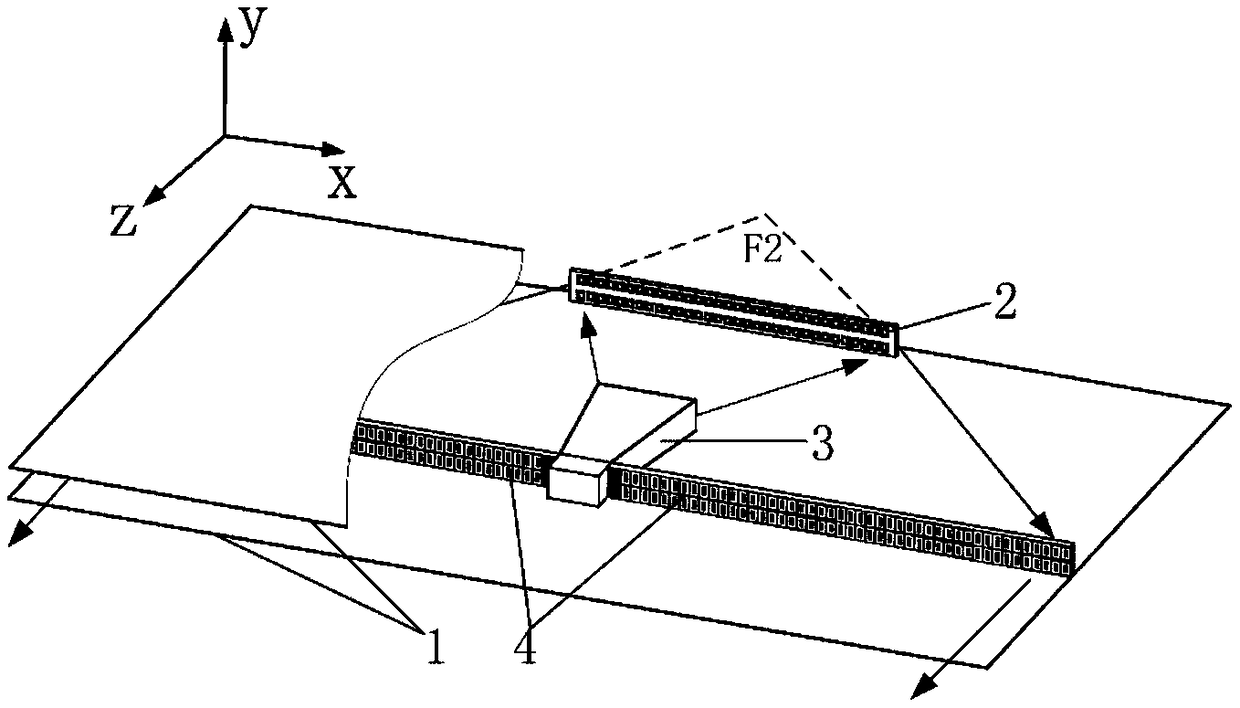
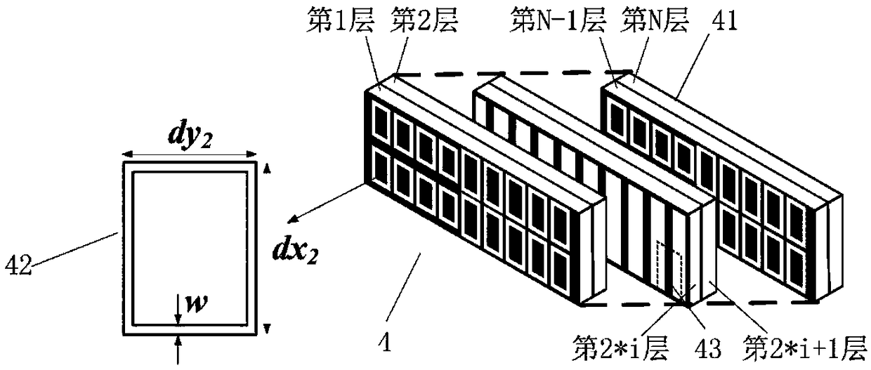
[0036] refer to figure 1 , the present invention includes a parallel slab waveguide 1, and a secondary reflector 2 and a feed 3 fixed between two metal plates of the parallel slab waveguide 1;

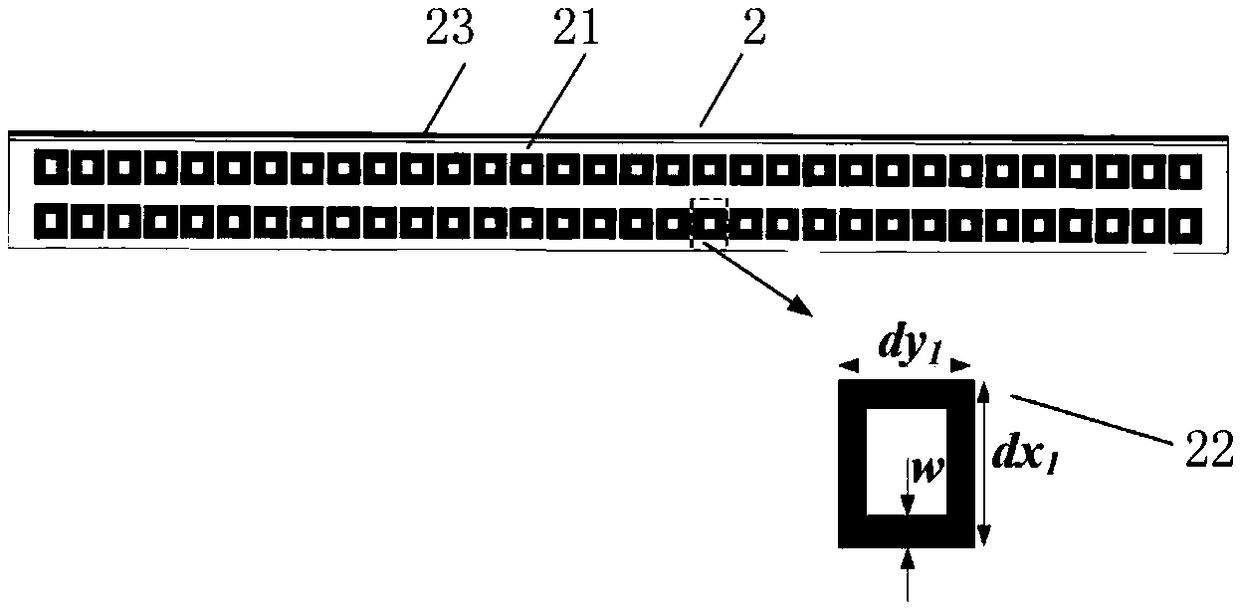
[0037] The secondary reflector 2 includes a first rectangular dielectric substrate 21, the surface of which is perpendicular to the two metal plates of the parallel planar waveguide 1, and 2×20 evenly arranged annular metal patches are printed on one side thereof 22, the other side is printed with a metal base plate 23;

[0038] The feed source 3 adopts a rectangular horn antenna structure, which is located on the side of the sub-reflector 2 where the ring-shaped metal patch 22 is printed, and its horn radiation port is parallel to the plate surface of the first rectangular dielectric substrate 21; the waveguide of the feed source 3 A main transmissio...


PUM


Abstract

The invention provides a metasurface-based transmissive Cassegrain antenna for solving the technical problem that effective radiation of electromagnetic waves is hindered due to the fact that a secondary reflector of a reflective Cassegrain antenna shields a main reflector in the prior art. The metasurface-based transmissive Cassegrain antenna comprises a parallel planar waveguide, a secondary reflector, a main transmitting mirror and a feed source, wherein the secondary reflector, the main transmitting mirror and the feed source are located between two metal plates of the parallel planar waveguide; multiple uniformly arranged annular metal patches are printed on one side surface of the secondary reflector and a metal bottom plate is printed on the other side surface; the main transmittingmirror is of a multilayer dielectric layer structure; multiple uniformly arranged annular gaps are etched at the front sides of an odd number of dielectric layers; multiple uniformly arranged metal strips are printed at the front sides of an even number of dielectric layers; multiple uniformly arranged annular gaps are etched at the back side of the last dielectric layer; a rectangular horn antenna structure is adopted by the feed source; and a phase jump metasurface structure constructed on the basis of a generalized Snell's theorem is adopted by the main transmitting mirror and the secondary reflector.

Description

technical field [0001] The invention belongs to the technical field of antennas, and relates to a Cassegrain antenna, in particular to a transmission type Cassegrain antenna with a planar structure realized by a phase mutation metasurface based on the generalized Snell theorem, which can be used in the microwave field. technical background [0002] The Cassegrain antenna adds a hyperboloid secondary reflector on the basis of a parabolic antenna. Electromagnetic waves pass through the secondary reflector and are reflected by the primary reflector to form a highly directional radiation pattern. Compared with ordinary parabolic antennas, its dual-mirror design can achieve the radiation performance of long-focus paraboloids with short-focus paraboloids, which is more advantageous in practical applications. On the one hand, the added sub-reflector makes it easier to design the surface field distribution, which can optimize the antenna radiation performance; on the other hand, sin...

Claims


Application Information

Patent Timeline
IPC IPC(8): H01Q15/14H01Q19/185H01Q1/50
CPCH01Q1/50H01Q15/14H01Q19/185
Inventor 杨锐杨佩李冬
Owner XIDIAN UNIV
Why Eureka
Try Eureka