Communication network time service method and system based on PTP time synchronization signal
A communication network and time synchronization technology, applied in the direction of time division multiplexing system, multiplexing communication, electrical components, etc., can solve the problems of single time service means, large environmental impact, and satellite navigation system susceptible to interference, etc., to achieve Guarantee the effect of high synchronization, safety and reliability
- Summary
- Abstract
- Description
- Claims
- Application Information
AI Technical Summary
Problems solved by technology
Method used
Image

Examples
Embodiment 1
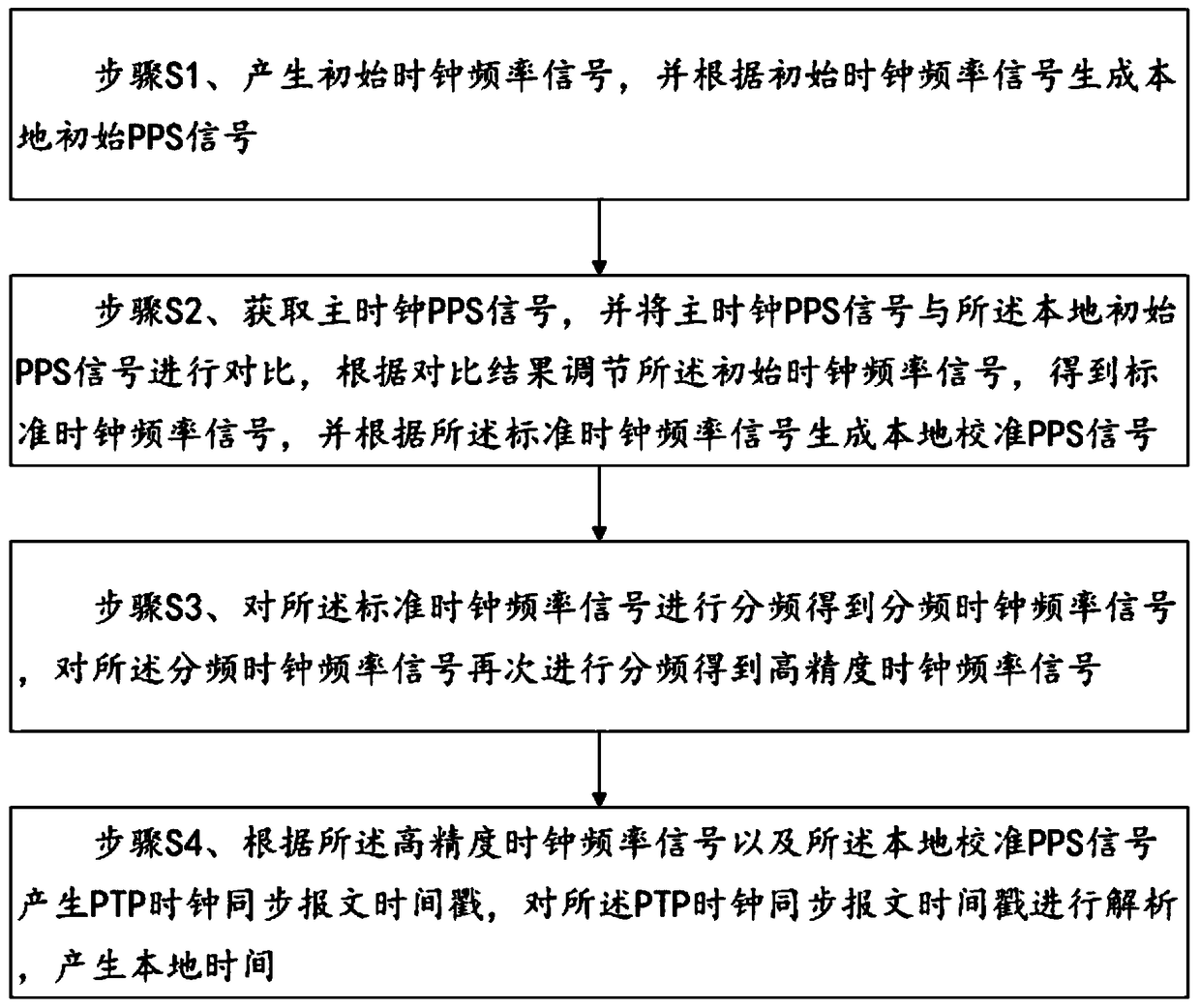
[0020] like figure 1 As shown, Embodiment 1 of the present invention provides a communication network timing method based on a PTP time synchronization signal, including the following steps:
[0021] Step S1, generating an initial clock frequency signal, and generating a local initial PPS signal according to the initial clock frequency signal;
[0022] Step S2, obtain the master clock PPS signal, and compare the master clock PPS signal with the local initial PPS signal, adjust the initial clock frequency signal according to the comparison result, obtain a standard clock frequency signal, and according to the standard clock frequency signal Generate a local calibration PPS signal;
[0023] Step S3, dividing the frequency of the standard clock frequency signal to obtain a frequency-divided clock frequency signal, and dividing the frequency of the frequency-dividing clock frequency signal again to obtain a high-precision clock frequency signal;
[0024] Step S4: Generate a time...
Embodiment 2
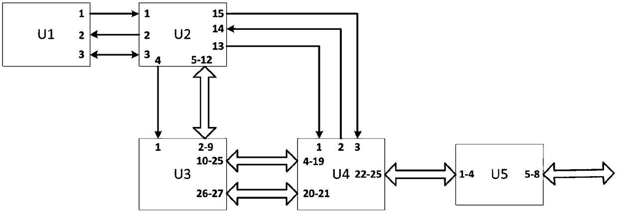
[0048] like figure 2 As shown, Embodiment 2 of the present invention provides a communication network timing system based on a PTP time synchronization signal, including a constant temperature crystal oscillator module U1, an FPGA module U2, a CPU module U3 and an Ethernet module U4; the constant temperature crystal oscillator module U1 passes through the The FPGA module U2 is electrically connected to the CPU module U3, and the FPGA module U2 is electrically connected to the Ethernet module U4 through the CPU module U3;
[0049] The constant temperature crystal oscillator module U1 is used to generate a standard clock frequency signal and send it to the FPGA module U2;
[0050] The FPGA module U2 is configured to generate a local calibration PPS signal according to the standard clock frequency signal, and divide the standard clock frequency signal to obtain a frequency-divided clock frequency signal;
[0051] The Ethernet module U4 is used to divide the frequency-divided cl...
PUM
 Abstract
Description
Claims
Application Information