Heat pipe backboard type data center

A data center and backplane-type technology, applied in the field of heat pipe backplane-type data centers, can solve the problems of complex control system, difficult control of air-conditioning system pipeline load and refrigerant flow, and less obvious energy-saving effect of heat dissipation information computer room, etc. , to achieve the effect of reduced fan power, small footprint, and increased heat transfer efficiency

Pending Publication Date: 2018-11-06
BEIJING FULLLINK OREITH TECH CO LTD
View PDF0 Cites 0 Cited by
  • Summary
  • Abstract
  • Description
  • Claims
  • Application Information

AI Technical Summary

Problems solved by technology

However, due to the dense distribution of cabinets in the information room, this method is easy to cause the pipeline load and refrigerant flow of the air conditioning system to be difficult to control, and the control system is more complicated; The energy saving effect of the information computer room is not obvious

Method used


Image

  • Heat pipe backboard type data center
  • Heat pipe backboard type data center
  • Heat pipe backboard type data center

Examples


specific Embodiment approach 1

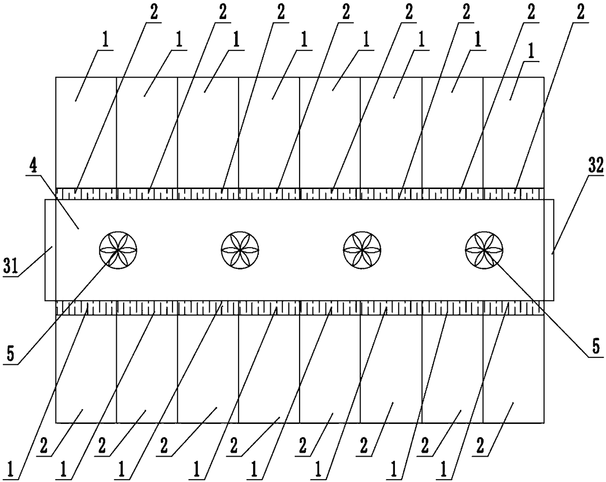
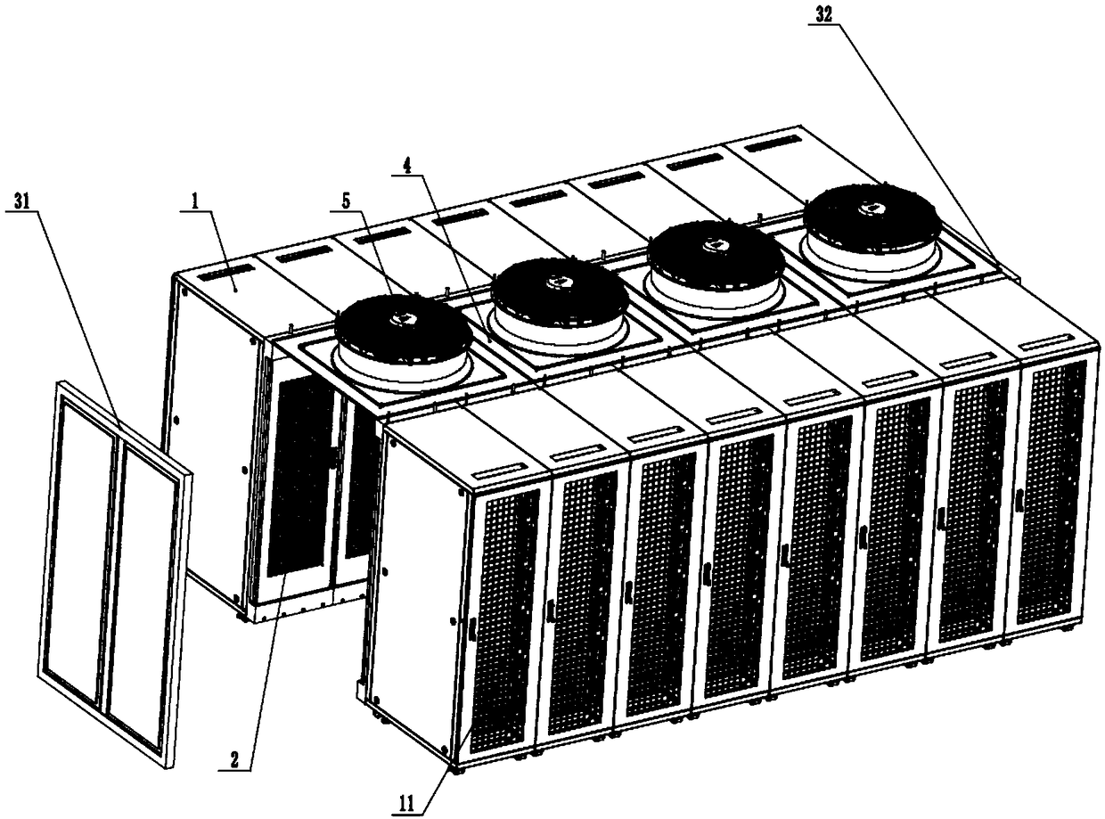
[0026] Such as figure 1 with 2 As shown, the heat pipe backplane data center of the present invention includes a plurality of cabinets 1, a number of backplane air conditioners 2 corresponding to the cabinets, a closed top cover 4, a front door 31, a rear door 32 and a plurality of fans 5; A plurality of cabinets 1 are formed in front and rear rows of cabinet groups, and the front row of cabinet groups and the rear row of cabinet groups are arranged side by side; each of the back panel air conditioners 2 is installed on the rear door of each corresponding cabinet 1, and the back panel air conditioners 2 Rotationally installed on one side of the rear door of the cabinet 1, and can be rotated by rotating the rear door; the front row cabinet group and the rear cabinet group are placed back to back, that is, the back panel air conditioner 2 on the front row cabinet group and the rear cabinet group A cold aisle is formed in the middle of the backplane air conditioner 2 on the row ...

specific Embodiment approach 2

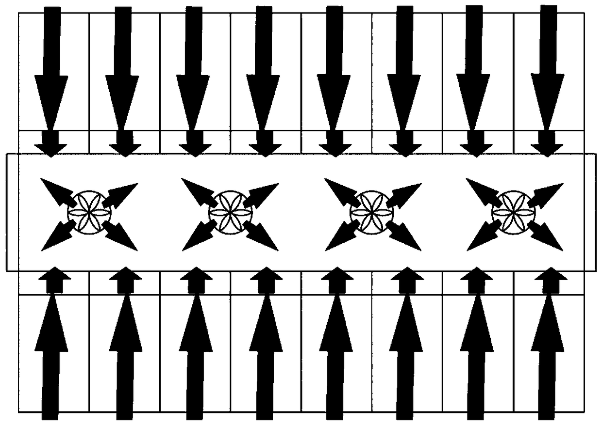
[0033] Please refer to Figure 4 , Figure 5 with Image 6 As shown, in this embodiment, the cabinet doors 11 of the front row cabinet group and the rear cabinet group are placed face to face, that is, each row of cabinet groups forms a closed door 11 with the closed top cover 4, the front door 31 and the rear end surface 32 respectively. cold aisle. The back panel air conditioner 2 is installed on the back door of the cabinet 1. The fan 5 sucks cold air from the environment and sends it into the cold aisle. The cold air enters the cabinet 1 to cool the electronic equipment through the cold aisle. The hot air blown from the cabinet 1 directly passes through the back panel air conditioner 2. The heat exchanger is cooled, so that the cooler air flow discharged from the back panel air conditioner 2 is recirculated into the environment. All the other parts are the same as the first embodiment, and the working method is also the same.


PUM


Abstract

The invention provides a heat pipe backboard type data center. The data center comprises a plurality of cabinets, a plurality of backboard air conditioners, and a plurality of fans, wherein the numberof the backboard air conditioners is identical to the number of the cabinets; the cabinets are arranged in a front row and a back row to form cabinet groups, and a front-row cabinet group and a rear-row cabinet group are arranged side by side; each backboard air conditioner is mounted on a rear door of the corresponding cabinet; the front-row cabinet group and the rear-row cabinet group are arranged back to back, so that a cooling passage is formed between the front-row cabinet group and the rear-row cabinet group; a closing cover top is mounted at the top of the cooling passage; a pluralityof fan mounting openings are formed in the closing cover top; and the fans are respectively mounted on the fan mounting openings in the sealing cover top. Therefore, the backboard air conditioners aremounted on the rear doors of the cabinets, hot air blown from the cabinets is directly cooled through heat exchangers of the backboard air conditioners, and cooled air enters the cooling passage andis sent to a surrounding environment through suction of the fans, so that cooler air flows that are exhausted from the cabinets can be recycled into the cabinets for cooling of electronic equipment.

Description

technical field [0001] The invention relates to the field of data centers, in particular to a heat pipe backplane data center. Background technique [0002] In recent years, there have been two major issues in data center heat dissipation: heat dissipation in high heat density situations and how to achieve energy-saving operation of data centers. [0003] In terms of high heat density: In recent years, with the development of data centers, the heat density of a single cabinet in the data center has become higher and higher, reaching 20kW / cabinet, or even higher. It is already very difficult to use traditional direct expansion air conditioners or chilled water machine room air conditioners. It is difficult to solve the heat dissipation problem of this kind of high heat density computer room, and it is easy to generate hot spots locally. [0004] In terms of energy consumption, with the development of data centers, the greater the heat, the greater the air volume. The existin...

Claims


Application Information

Patent Timeline
Patent Type & Authority Applications(China)
IPC IPC(8): H05K7/20
CPCH05K7/20827H05K7/20745
Inventor 孙继东丁式平何慧丽杨赢喜张贺
Owner BEIJING FULLLINK OREITH TECH CO LTD
Why Eureka
Try Eureka