

Blanking system for biomass pellet furnace
A biomass pellet and blanking technology, which is applied in the direction of fuel supply, combustion method, block/powder supply/distribution, etc., can solve the problems of increasing motor pressure, inability to achieve uninterrupted feeding, and low blanking rate. , to avoid the effect of jamming
- Summary
- Abstract
- Description
- Claims
- Application Information
AI Technical Summary
Problems solved by technology
Method used
Image

Examples
Embodiment 1
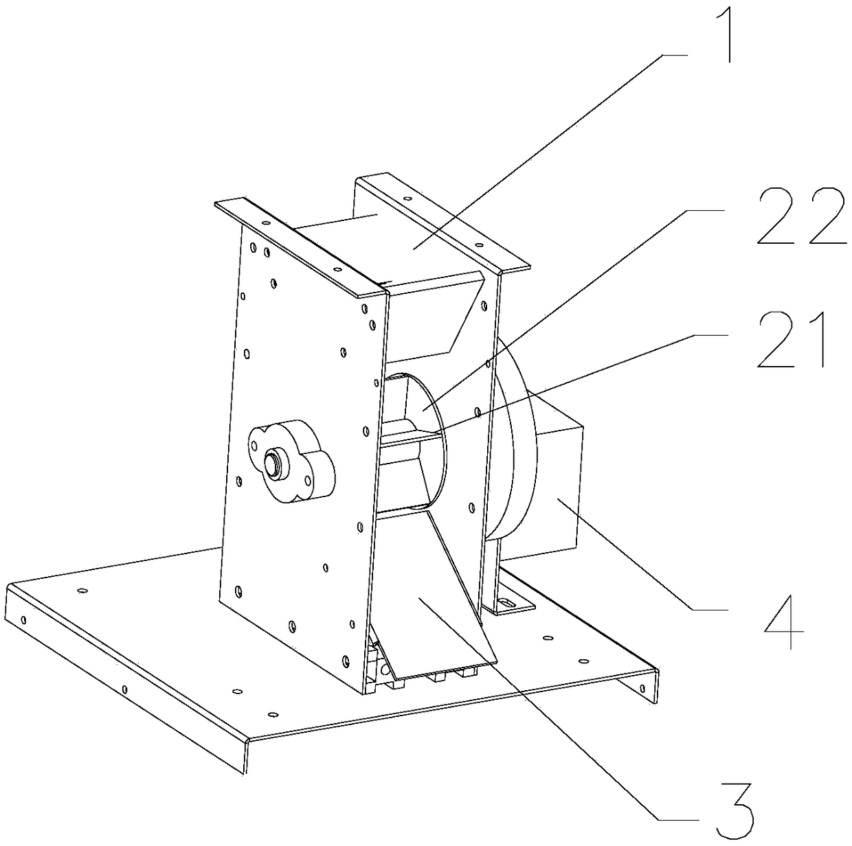
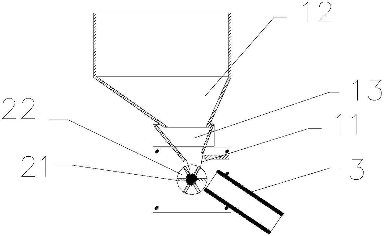
[0037] A feeding system for a biomass pellet furnace, comprising a hopper 1, a feeding chute 2 arranged below the outlet of the hopper 1, a feeding channel 3 arranged below the outlet of the feeding chute 2, and a feeding chute 2 for controlling The motor 4 that rotates; the feeding chute 2 is cylindrical, and the shaft of the cylinder is the axis of rotation, and rotates perpendicular to the ground plane. The silo 22 is opened outward; a combustion device feed port is arranged below the outlet of the lower material channel 3 .
[0038] There is an included angle of 60° between the lower silo partition 21 and the cutting surface of the chute 2 rotation axis, and the inclination direction of the lower hopper partition 21 is the same as the rotation direction of the lower chute 2 .
[0039] The lower end of the hopper 1 is provided with an elastic reed I11, and the free end of the elastic reed I11 extends into the lower bin 22.
[0040] The lower end of the entrance of the disc...
Embodiment 2
[0044] A blanking system for a biomass pellet stove, the difference from Example 1 is:
[0045] The blanking system also includes a blanking volume control panel, which is obliquely arranged at the contact between the hopper 1 and the blanking chute 2; The elastic reed and the extension spring arranged on the lower surface of the control board are used to control the inclination angle of the blanking amount control board.
[0046] The elastic reed of blanking amount control plate is made up of many reeds, and every reed is made of upper strata reed and lower stratum reed, and the length of upper stratum reed is greater than the length of lower stratum reed.
Embodiment 3
[0048] A blanking system for a biomass pellet stove, the difference from Example 1 is:
[0049] The feeding system also includes a cam and a lever, which are used to move the fuel in the hopper 1. The cam is arranged on the rotating shaft, located on both sides of the feeding tank, and rotates synchronously with the feeding tank. The cam is provided with protrusions and depressions; the lower end of the driving rod The cam is slidably connected, and translates up and down with the rotation of the cam, and the upper end stirs the fuel in the hopper 1. A shift fork is arranged at the upper end of the shift lever.
PUM
 Abstract
Description
Claims
Application Information