
Movable device displacement measurement method as well as rough mill and gate footstep shear using same

A technology of movable devices and measuring methods, which is applied in the direction of shearing devices, length measuring devices, and accessories of shearing machines, etc., can solve the problems of closed-loop control of measurement results, difficulty in eliminating gaps, inaccurate measurement, etc., and reduce camber phenomenon , Overcome the position measurement error and improve the effect of measurement accuracy

Inactive Publication Date: 2018-11-13
NANJING IRON & STEEL CO LTD
View PDF10 Cites 1 Cited by
  • Summary
  • Abstract
  • Description
  • Claims
  • Application Information

AI Technical Summary

Problems solved by technology

However, the displacement measured by the rotary encoder is often difficult to eliminate all gaps due to the limitation of the mechanical structure, resulting in inaccurate measurement and large errors, and the measurement results cannot be used for precise closed-loop control

Method used


Image

  • Movable device displacement measurement method as well as rough mill and gate footstep shear using same

Examples


Embodiment 1

[0023] Embodiment 1. In this embodiment, the position of the front side guide plate of the rough rolling mill of a medium plate factory is measured in real time, and the maximum width of the outer contour of the clamped steel plate is calculated. The front side guide plate of the rough rolling mill is located in front of the four-high reversible rolling mill and above the tapered work roll table in front of the machine, and is used to cooperate with the turning of the rolled piece, measure the width, push and clamp the rolled piece, and make it centered on the rolling center line to ensure smooth entry and exit of the rolled piece rolling mill. It is a mechanical speed-increasing rack-and-pinion side guide plate driven by a hydraulic cylinder. It is mainly composed of main transmission box, return transmission box, push plate, side guide box, speed measuring device, pull rod device, hydraulic pressure, dry oil piping and other components. The main transmission box is composed...

Embodiment 2

[0025] Embodiment 2, the application of this embodiment to the measurement of the width of steel plate sheared by the 3# guillotine in a medium plate factory. There are 4 guillotine scissors in the medium plate factory to cut the head, tail, width and edge of the steel plate respectively. The 3# shear is for the final width sizing. It is necessary to ensure that the width of the finished steel plate meets the order requirements. The original system used the installation scale to measure the width. As the value of the scale changes with the movement of the push head, the operator determines the plate width through the indicated value of the scale to cut the width. The error is 6mm. Different operating tools have different reading deviations. Width has a greater influence, which affects the cutting quality.

[0026] After applying the measurement method described in the present invention, the wire-drawing encoder is installed on the fixed base of the edge pushing machine, and th...


PUM


Abstract

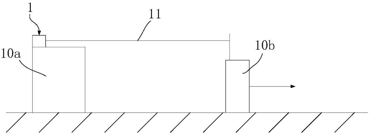
The invention discloses a movable device displacement measurement method as well as a rough mill and a gate footstep shear using the same. According to the measurement method, a stay wire coder and aPLC system are provided; the stay wire coder is installed at the fixed end of a movable device; a stay wire of the stay wire coder is fixed to the movable end of the movable device so that the stay wire moves with the movable end; when the stay wire moves with the movable end, the stay wire coder is used for generating signal changes; a signal template of the PLC system is used for acquiring the variation of signals; and displacement changes of the movable end are obtained by calculation. The method effectively overcomes position measurement errors caused by mechanical clearances. After usingthe method, the rough mill can realize precise measurement of the width of a side guide plate, reduces the phenomenon of cambering generated in a rolling process and improves the product quality. After using the method, the gate footstep shear improves the width measurement precision of a steel plate.

Description

technical field [0001] The invention relates to a displacement measurement technology, in particular to a method for measuring the displacement of a movable device by using a wire-drawing encoder and a rough rolling mill and a guillotine shear applying the method. Background technique [0002] At present, in the production process of medium and thick plates, the moving position of the device is mostly measured by various sensors. For example, equipment driven by hydraulic cylinders mostly uses linear displacement sensors, and those with rotary mechanisms can use rotary encoders. The linear displacement sensor has the characteristics of simple and intuitive measurement and high precision, and is widely used. However, the displacement measured by the rotary encoder is often difficult to eliminate all gaps due to the limitations of the mechanical structure, resulting in inaccurate measurement and large errors, and the measurement results cannot be used for precise closed-loop ...

Claims


Application Information

Patent Timeline
Patent Type & Authority Applications(China)
IPC IPC(8): B23D17/00B23D33/12B21B38/04
CPCB21B38/04B23D17/00B23D33/12
Inventor 赵桂琴潘德军钟杨嵇翔
Owner NANJING IRON & STEEL CO LTD
Learn More