Circulating fluidized bed boiler bottom slag waste heat recovery device

A technology of circulating fluidized bed and recovery device, which is applied to fluidized bed combustion equipment, lighting and heating equipment, and fuel burning in a molten state, etc. It can improve the heat transfer coefficient, reduce the flow resistance and prolong the heat transfer time.

Active Publication Date: 2018-11-13
CHONGQING UNIV
View PDF6 Cites 3 Cited by
  • Summary
  • Abstract
  • Description
  • Claims
  • Application Information

AI Technical Summary

Problems solved by technology

The drum-type slag cooler has loose requirements on the particle size of the bottom slag and is reliable in operation, but it cannot recover fine ash, and can only obtain condensed water not exceeding 100°C as the heat exchange medium, and the recovery rate of waste heat is only about 10%. When the amount is large, a large amount of condensed water needs to be supplied
In the fluidized bed slag cooler, the gas-solid mixing characteristics of the bottom slag and the fluidized air are good, the heat transfer coefficient is high, and the fine ash can be separated and sent back to the furnace. However, considering wear and tear, the adjustable range of the fluidization air volume and the particle size of the bottom slag is limited. At the same time, due to the mixed heat exchange of wind and slag, the air temperature at the outlet of the fluidized bed slag cooler is between 300-400°C. When the amount of bottom slag increases, the fluidization air volume required to cool the bottom slag also increases. The overall gas-solid flow and heat transfer effects are also gradually increasing
Although the above problems have been solved to a certain extent by using a moving bed heat exchanger (CN201710238950.1), the particle size distribution of the bottom slag has a great influence on the operation of this type of moving bed heat exchanger. , the bed resistance increases significantly, and the overall energy consumption increases sharply
[0004] In general, the existing bottom slag cooling and waste heat recovery devices can only obtain water with a temperature not exceeding 100°C and hot air at 300-400°C, and cannot obtain high-efficiency and high-quality waste heat recovery media. , it cannot help to maintain the concentration of fine particles in the dilute phase zone in the furnace, and at the same time, the energy consumption of air and water required for cooling the bottom slag is huge

Method used


Image

  • Circulating fluidized bed boiler bottom slag waste heat recovery device
  • Circulating fluidized bed boiler bottom slag waste heat recovery device
  • Circulating fluidized bed boiler bottom slag waste heat recovery device

Examples


Embodiment 1

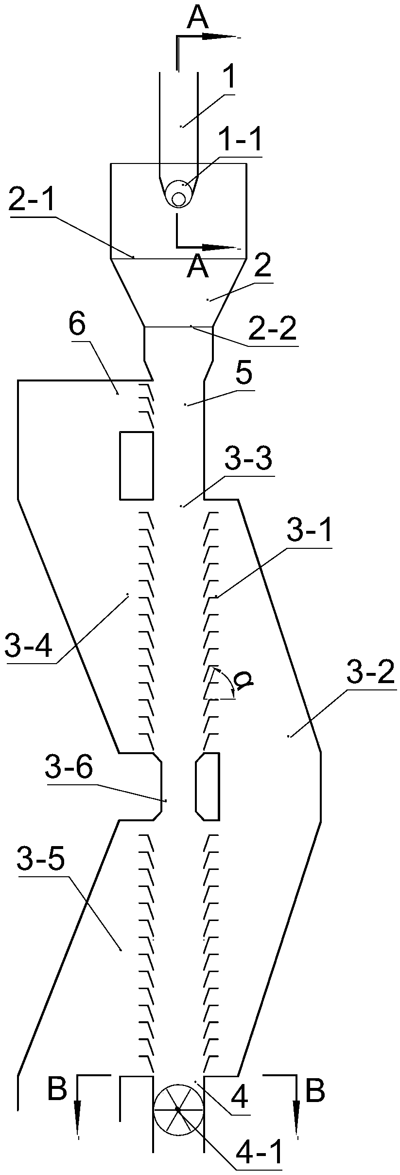
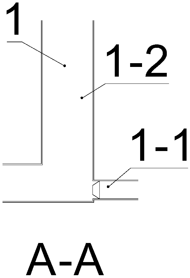
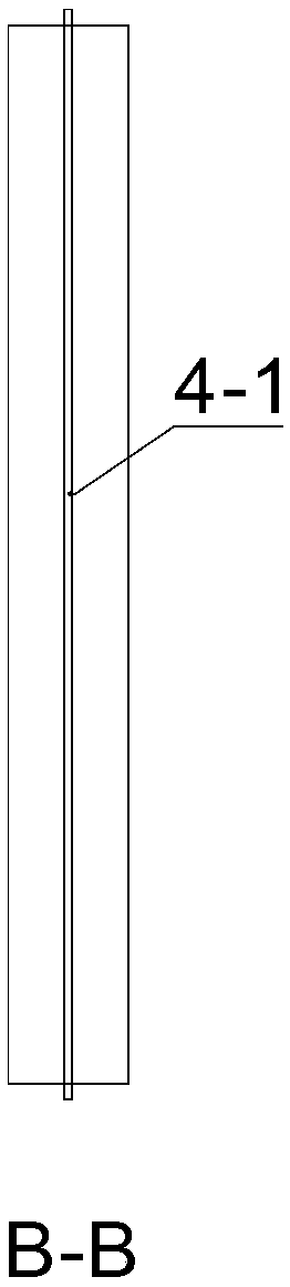
[0017] The structure of a circulating fluidized bed boiler bottom slag waste heat recovery device involved in this embodiment is as follows: Figure 1-Figure 4 As shown, it includes an L-type ash control valve 1, a sorting section pipeline 2, a cross-flow moving bed heat exchanger 3 and a slag discharge device 4, wherein the length of the standpipe section 1-2 of the L-type ash control valve 1 is 2m, and the air flow for introducing The ratio of the length of the tube 1-1 extending into the valve body to the length of the standpipe section 1-2 is 0; the sorting section pipeline 2 is a section of necking pipeline with a large top and a small bottom, and the upper part of the sorting section pipeline 2 is the sorting section inlet 2-1, Its lower part is the sorting section outlet 2-2, the ratio of the cross-sectional area of ​​the sorting section inlet 2-1 to the sorting section outlet 2-2 is 2, and the sorting section outlet 2-2 is 1 time of the cross-sectional area of ​​the bot...

Embodiment 2

[0021] The structure of a circulating fluidized bed boiler bottom slag waste heat recovery device involved in this embodiment is as follows: Figure 5-Figure 6As shown, it includes an L-type ash control valve 1, a sorting section pipeline 2, a cross-flow moving bed heat exchanger 3 and a slag discharge device 4, wherein the length of the standpipe section 1-2 of the L-type ash control valve 1 is 2m, and the air flow for introducing The ratio of the length of the tube 1-1 extending into the valve body to the length of the standpipe section 1-2 is 0; the sorting section pipeline 2 is a section of necking pipeline with a large top and a small bottom, and the upper part of the sorting section pipeline 2 is the sorting section inlet 2-1, Its lower part is the sorting section outlet 2-2, the ratio of the cross-sectional area of ​​the sorting section inlet 2-1 to the sorting section outlet 2-2 is 2, and the sorting section outlet 2-2 is 1 time of the cross-sectional area of ​​the bott...


PUM


Abstract

A circulating fluidized bed boiler bottom slag waste heat recovery device comprises an L-shaped ash control valve (1), a sorting section pipeline (2), a cross-flow moving bed heat exchanger (3) and aslag discharging device (4), wherein the sorting section pipeline (2) is a big-end-up opening contraction pipeline, the upper portion of the sorting section pipeline (2) is provided with a sorting section inlet (2-1), and the lower portion of the sorting section pipeline (2) is provided with a sorting section outlet (2-2); the cross-flow moving bed heat exchanger (3) is composed of a separation flow guide plate (3-1), a cooling flue (3-2) and a bottom slag channel (3-3), the upper portion of a cross-flow moving bed is connected with the sorting section pipeline outlet through a slag feeding pipe (5), and the width of the bottom slag channel (3-3) of the cross-flow moving bed is 200-2000 mm; the bottom slag flowing speed is controlled by the slag discharging device (4), meanwhile, after being pressurized by a recycling fan, flue gas transversely passes through the bottom slag channel in an S shape through the separation flow guide plate (3-1), and the included angle (alpha) between theinclined section of the separation flow guide plate (3-1) and the horizontal direction is 20-80 degrees. According to the circulating fluidized bed boiler bottom slag waste heat recovery device, the recirculating flue gas is adopted as a heat exchange medium, the vast majority of heat of the bottom slag is recovered back into a boiler, continuous stable operation of the waste heat recovery deviceis ensured, boiler ash slag physical heat losses are decreased, and the boiler efficiency is improved.

Description

Technical field: [0001] The invention relates to the technical field of circulating fluidized bed boilers, in particular to a device for cooling high-temperature bottom slag and recovering waste heat of circulating fluidized bed boilers. Background technique: [0002] When the circulating fluidized bed boiler burns fuel with medium and low calorific value, especially fuel with high ash content and high hardness such as coal gangue, the amount of bottom slag will increase significantly, and the physical heat loss of ash and slag will be as high as 3%. For coal fuels with low calorific value below 2000kcal / kg, the physical heat loss of ash and slag can even reach 5%-15%. Guaranteed. Several commonly used slag coolers have solved the above problems to varying degrees, but there are problems such as the inability to recover high-quality heat exchange media and the inability to efficiently utilize the recovered heat. [0003] At present, the commonly used slag coolers are mainl...

Claims


Application Information

Patent Timeline
Patent Type & Authority Applications(China)
IPC IPC(8): F23C10/24
Inventor 卢啸风郑雄李建波杨帆王泉海杨宇刘卓陈子曦郑越
Owner CHONGQING UNIV
Why Eureka
Try Eureka