
Collimator pose regulating device and method for free-form surface laser assisted milling

A laser-assisted and adjusting device technology, which is applied in milling machine equipment details, milling machine equipment, metal processing equipment, etc., can solve the problems that laser cannot accurately preheat workpieces, laser-assisted milling processing fails, and laser spot heating cannot be adjusted. The effect of small space, compact structure layout and small size

Active Publication Date: 2018-11-16
HUAZHONG UNIV OF SCI & TECH
View PDF6 Cites 9 Cited by
  • Summary
  • Abstract
  • Description
  • Claims
  • Application Information

AI Technical Summary

Problems solved by technology

Therefore, when the tool path changes, the fixed collimator installed on the milling machine cannot adjust the laser spot to heat the workpiece material in front of the tool, making it impossible for the laser to accurately preheat the workpiece, which eventually leads to the failure of laser-assisted milling.

Method used


Image

  • Collimator pose regulating device and method for free-form surface laser assisted milling
  • Collimator pose regulating device and method for free-form surface laser assisted milling
  • Collimator pose regulating device and method for free-form surface laser assisted milling

Examples


Embodiment Construction

[0033] In order to make the objectives, technical solutions and advantages of the present invention clearer, the present invention will be further described in detail below with reference to the accompanying drawings and embodiments. It should be understood that the specific embodiments described herein are only used to explain the present invention, but not to limit the present invention. In addition, the technical features involved in the various embodiments of the present invention described below can be combined with each other as long as they do not conflict with each other.

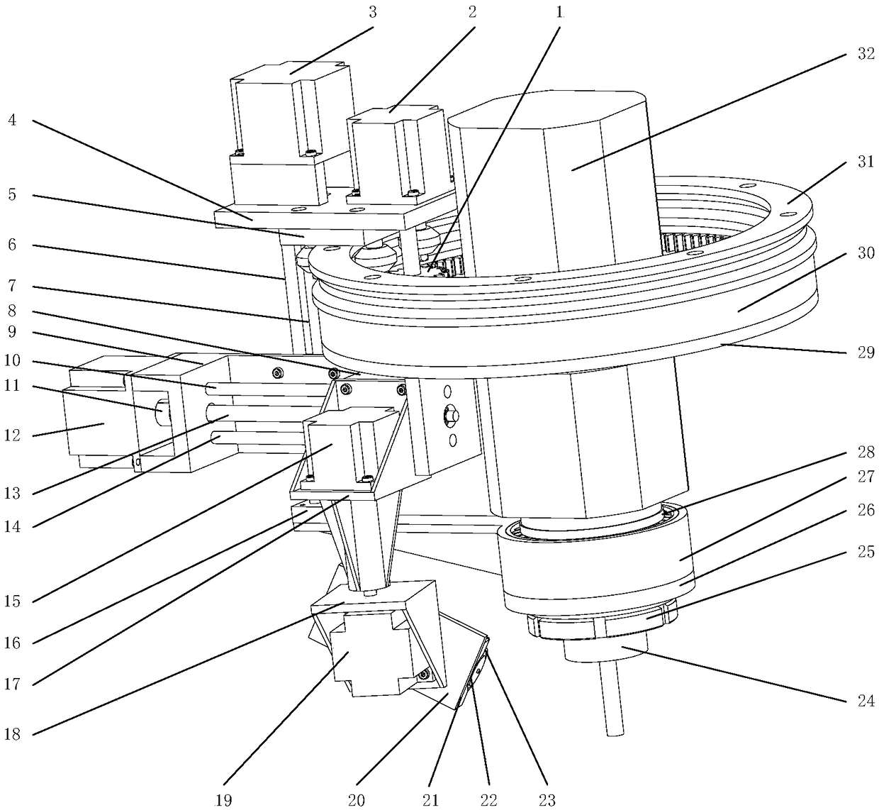
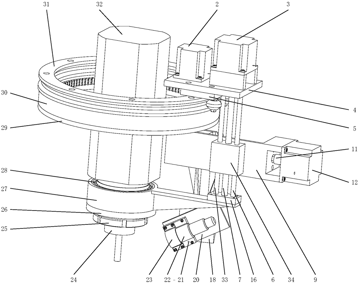
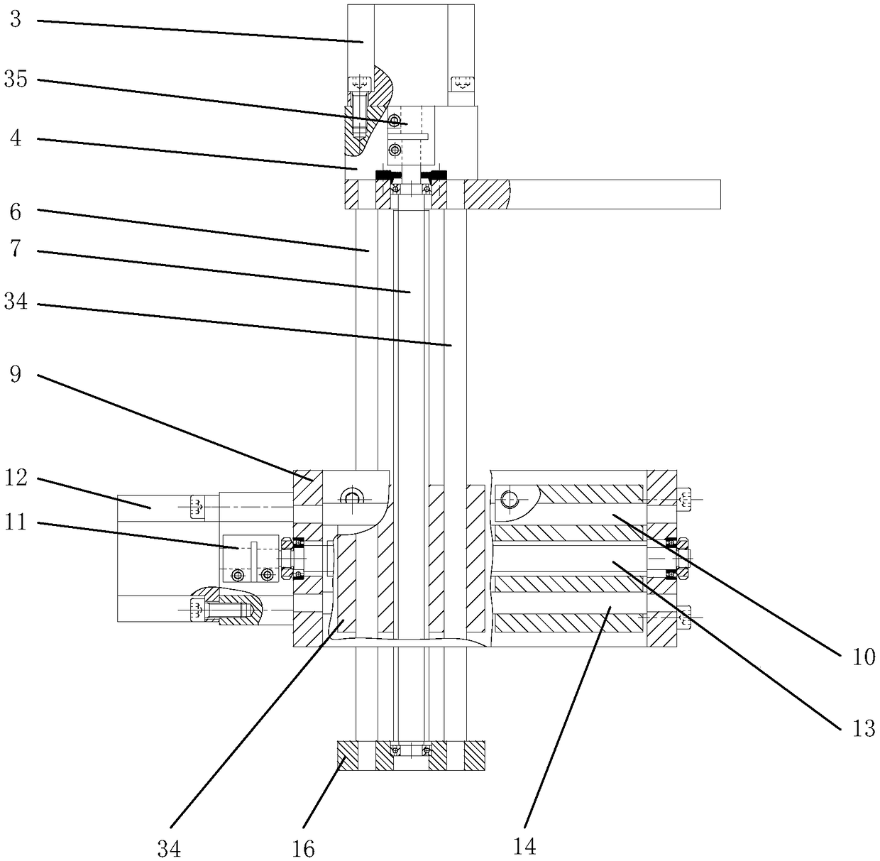
[0034] like figure 1 As shown, an embodiment of the present invention provides a collimator position and attitude adjustment device for free-form surface laser-assisted milling, which includes an internal meshing gear mechanism, a circular slide rail 31, and a cross slide mechanism. The device can realize In the process of free-form surface laser-assisted milling, the laser spot is adjusted in real...


PUM


Abstract

The invention belongs to the field of pose regulation of collimators and discloses a collimator pose regulating device and a collimator pose regulation method for free-form surface laser assisted milling. The device comprises an inside engaged gear, a circular sliding rail and a cross sliding table mechanism; the inside engaged gear comprises a main gear and a pinion, wherein the main gear is installed outside a main shaft of a machine tool in a sleeving manner; the pinion is internally engaged with the main gear; the lower portion of the main shaft of the machine tool is connected with a cutter; the main gear is fixed to the main shaft of the machine tool; the pinion is connected with a first servo motor; the circular sliding rail is installed outside the main shaft of the machine tool ina sleeving manner; the cross sliding table mechanism is positioned by the side of the main gear, is connected with the first servo motor and can do circular motion with motion of the pinion under theguidance of the circular sliding rail; a collimator is installed on the cross sliding table mechanism by virtue of a mounting and fixing mechanism; and the method is implemented by utilizing the collimator pose regulating device. The collimator pose regulating device disclosed by the invention can be used for regulating a laser spot in real time according to any cutter moving route so that the laser spot can be always positioned at a specified position of a material in front of the cutter.

Description

technical field [0001] The invention belongs to the field of collimator pose adjustment, and more particularly relates to a collimator pose adjustment device and method for laser-assisted milling of free-form surfaces. Background technique [0002] In recent years, laser-assisted milling technology has developed rapidly. During laser-assisted milling, the high-power laser is focused on the workpiece material in front of the cutting area, and the workpiece material is locally heated to a higher temperature in a short period of time before the material is removed, so that the cutting area of ​​the material to be processed is heated and softened. Thus, the yield strength of the workpiece material is effectively reduced, the cutting performance is improved, and the machining surface quality is improved while improving the machining efficiency. [0003] However, in the current laser-assisted milling process, the fixed collimator is connected to the milling machine to perform las...

Claims


Application Information

Patent Timeline
Patent Type & Authority Applications(China)
IPC IPC(8): B23C3/00B23P25/00B23C9/00
CPCB23C3/00B23C9/00B23P25/00B23P25/003B23P25/006
Inventor 闫蓉彭芳瑜杜鹏乐曾浩浩张明锴胡甜甜汪伟唐小卫
Owner HUAZHONG UNIV OF SCI & TECH
Learn More