Electric spark machine tool machining system

A technology of electric discharge machine tool and processing system, which is applied in the direction of metal processing equipment, manufacturing tools, auxiliary devices, etc., and can solve problems such as shaking of guide rails, poor welding effect, and inability to automatically correct the position of guide rails.

Active Publication Date: 2018-11-16
SHANDONG LIAOCHENG DERUN EMT DEVING
View PDF5 Cites 5 Cited by
  • Summary
  • Abstract
  • Description
  • Claims
  • Application Information

AI Technical Summary

Problems solved by technology

[0004] In order to solve the above problems, the present invention provides an electric discharge machine tool processing system, which can solve the problems existing in the welding of the guide rail of the electric discharge machine tool, such as the inability to fix the guide rail during the welding of the guide rail, the inability to automatically correct the position of the guide rail, and the welding of the guide rail. When the guide rail is welded, the welding slag will splash everywhere, the welding angle will change during the guide rail welding, resulting in poor welding effect, the end of the welding rod may stick to the machine tool when it is discarded, and the guide rail cannot be automatically processed after welding. ; It can realize the functions of stably supporting and fixing the guide rail of the EDM machine tool, automatic welding and post-welding treatment of the guide rail. The welding slag will not splash everywhere when the guide rail is welded, the welding angle will not change when the guide rail is welded, the welding effect is good, the electrode end can be recovered, and the guide rail can be automatically processed after welding, etc.

Method used


Image

  • Electric spark machine tool machining system
  • Electric spark machine tool machining system
  • Electric spark machine tool machining system

Examples


Embodiment Construction

[0032] In order to make it easy to understand the technical means, creative features, objectives and effects achieved by the present invention, the present invention will be further explained below in conjunction with specific drawings. It should be noted that the embodiments in this application and the features in the embodiments can be combined with each other if there is no conflict.

[0033] Such as Picture 9 As shown, the existing EDM machine tool guide rail is placed horizontally on the machine bed, and then the machine tool guide rail is connected to the machine bed by welding.

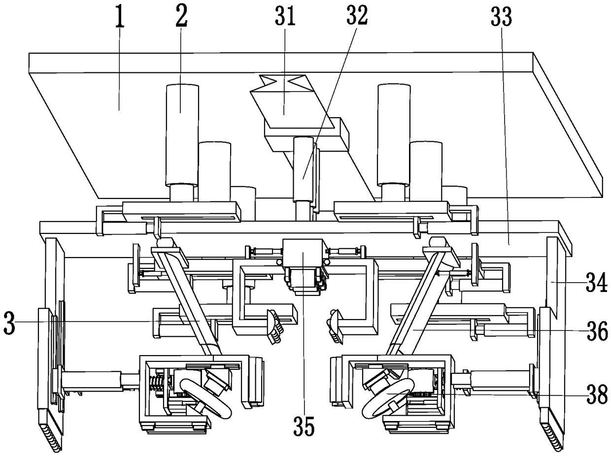
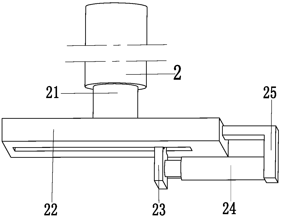
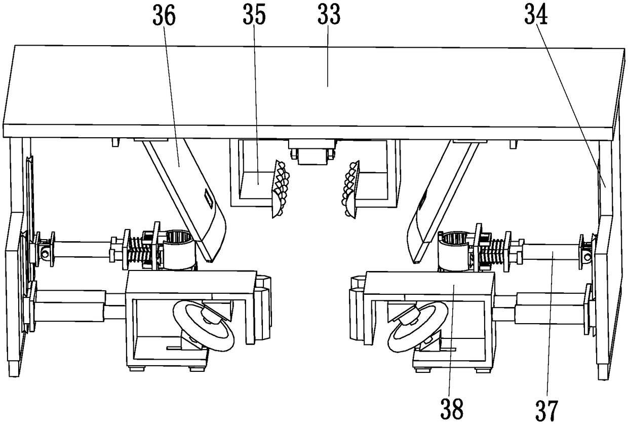
[0034] Such as Figure 1 to Figure 8 As shown, the EDM machining system includes a supporting top plate 1, a positioning mechanism 2 and a welding device 3. The positioning mechanism 2 is symmetrically installed on the bottom of the supporting top plate 1, and the welding device 3 is installed on the lower end surface of the middle of the supporting top plate 1. on.

[0035] The positioning mechanis...


PUM


Abstract

The invention relates to an electric spark machine tool machining system which comprises a supporting top plate, positioning mechanisms and a welding device. The positioning mechanisms are symmetrically mounted at the bottom of the supporting top plate; the welding device is mounted on the lower end face of the middle of the supporting top plate; the positioning mechanisms comprise positioning multi-stage push rods, positioning pressing plates, positioning plates, pushing push rods and push rod connecting frames; and the welding device comprises a welding electric sliding block, a welding position push rod, a welding supporting plate, welding side plates, a sliding mechanism, baffle mechanisms, welding mechanisms and clearing and polishing mechanisms. According to the electric spark machine tool machining system, the difficult problems that when a guiding rail of an existing electric spark machine tool is welded, the position of the guiding rail cannot be automatically corrected, the guiding rail shakes during welding, welding slag splashes everywhere during welding of the guiding rail, when the guiding rail is welded, the welding angle is changed, consequently the welding effect is poor, when discarded, welding rod ends are likely to be pasted to the machine tool, and post-welding treatment cannot be automatically conducted on the guiding rail can be solved.

Description

Technical field [0001] The invention relates to the technical field of EDM machine tool processing, in particular to an EDM machine tool processing system. Background technique [0002] EDM machine tool is a kind of machine tool equipment that uses the principle of electric discharge to process metal parts to process metal parts; because the principle of EDM is different from the principle of ordinary metal cutting, the EDM machine is similar to ordinary metal cutting machine tools. The structure is different. First, it has a large-energy pulse power supply device to provide energy for the generation of electric sparks. The main function is to generate repetitive high-intensity electric pulses on the tool electrode and the workpiece electrode to generate discharge electric sparks; secondly, because of the electric discharge machining When there is no direct contact between the tool and the workpiece, there is no obvious cutting force, so the EDM machine tool is not equipped with...

Claims


Application Information

Patent Timeline
Patent Type & Authority Applications(China)
IPC IPC(8): B23K31/02B23K37/04B23K37/08B23K37/00
CPCB23K31/02B23K37/00B23K37/0443B23K37/08
Inventor 李鸿梁荣
Owner SHANDONG LIAOCHENG DERUN EMT DEVING
Why Eureka
Try Eureka