Optical imaging system based on beam splitter prisms and ultrahigh frame frequency imaging method

An optical imaging system and beam-splitting prism technology, applied in optics, optical components, high-speed photography, etc., can solve the problem that it is difficult to meet the requirements of resolution and higher frame rate, it is difficult to obtain clear and delicate information of the target, and the application is limited. range and other issues, to achieve the effects of enhanced environmental adaptability, light weight, and high registration accuracy

Active Publication Date: 2018-11-16
AEROSPACE DONGFANGHONG SATELLITE
View PDF7 Cites 5 Cited by
  • Summary
  • Abstract
  • Description
  • Claims
  • Application Information

AI Technical Summary

Problems solved by technology

[0003] Traditional high-speed cameras can achieve very high frame rates, but most of them use film as the photosensitive element, and the system has scanning moving parts, which not only makes the system bulky, but also limits its application range
There is a restrictive relationship between the frame rate and resolution of digital high-speed cameras. High resolution will inevitably lead to a decrease in frame rate. Generally, the frame rate is low, only a few hundred to several thousand frames, which is difficult to meet the requirements for resolution and resolution in practical applications. The need for higher frame rates
The traditional ultra-high-speed framing imaging system mostly uses the receiving system of ICCD or image intensifier as the photodetector. This kind of imaging device has low resolution and large pixel size, which makes it difficult to obtain clearer and more delicate information of the target.

Method used


Image

  • Optical imaging system based on beam splitter prisms and ultrahigh frame frequency imaging method
  • Optical imaging system based on beam splitter prisms and ultrahigh frame frequency imaging method
  • Optical imaging system based on beam splitter prisms and ultrahigh frame frequency imaging method

Examples


Embodiment Construction

[0030] The present invention will be described in further detail below in conjunction with embodiment.

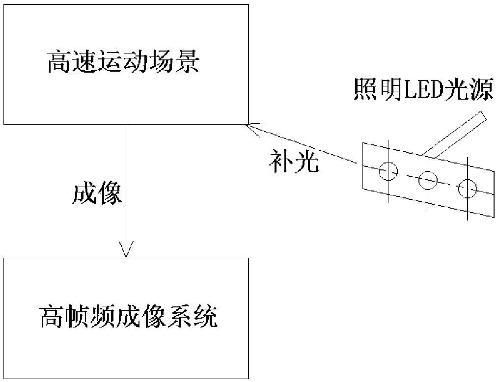
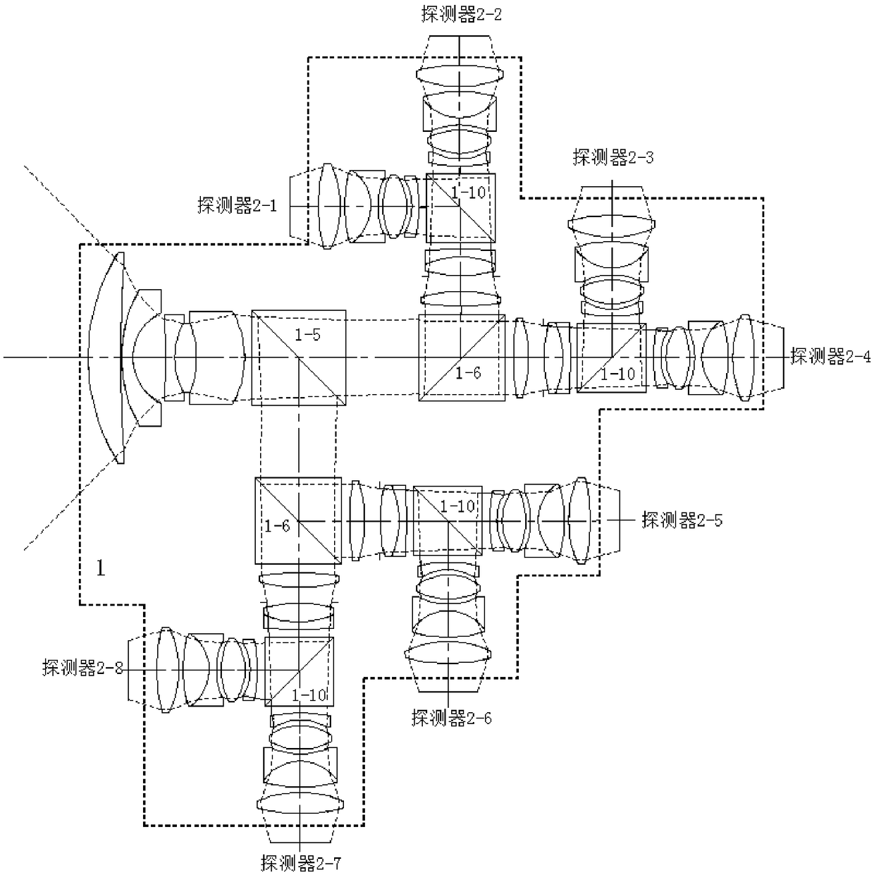
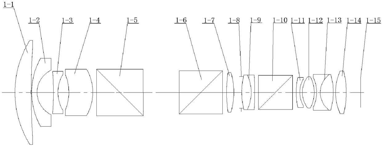
[0031] The high-resolution high-frame-rate imaging system involved in this embodiment is mainly composed of an eight-channel framing optical system 1, a high-resolution imaging detector assembly 2, and an LED lighting source. The system composition is as follows: figure 1 shown. Main technical index that the present invention can realize:

[0032] (1) Spectral range: 400nm~750nm

[0033] (2) Resolution: 1600×80

[0034] (3) Horizontal viewing angle: 90°

[0035] (4) Frame rate: 10 5 fps

[0036] The working principle of the high-resolution ultra-high frame rate imaging system: After the beam enters the optical system, multiple beam-splitting prisms in the optical system are cleverly used to split the light, and the incident light energy is divided into eight equal parts, which are respectively imaged on eight CMOS detectors. On the device, the synchronization control ...


PUM


Abstract

The invention discloses an optical imaging system based on beam splitter prisms and an ultrahigh frame frequency imaging method. The optical imaging system comprises an optical system and detector assemblies, wherein the beam splitter prisms are contained in the optical system; after a beam enters into the optical system, the beam is split through the beam splitter prisms in the optical system andis finally imaged on the detector assemblies respectively, simultaneously, the detector assemblies are controlled to carry out exposure in sequence so as to realize the high frame frequency imaging of a scene; the beam splitter prisms are arranged inside the optical system, and eight imaging light paths formed after the beam passes through every beam splitter prism are completely the same. The conflict between high resolution and frame frequency is solved, and the system has the characteristics of high frame frequency, high solution, compact structure, good imaging, convenience in use, high environmental suitability and the like.

Description

technical field [0001] The invention belongs to the technical field of high-speed photography, and relates to an optical imaging system based on a dichroic prism and an ultra-high frame rate imaging method. Background technique [0002] High-speed photography technology is an effective method to study the motion of high-speed objects. Compared with traditional photography, high-speed photography has high time resolution ability and can track and record the rapid change process. At present, high-speed photography has been widely used in industries and fields such as physics, biology, medicine, military affairs, and sports. Kinetics, gymnastics and other aspects play an extremely important role. [0003] Traditional high-speed cameras can achieve a very high frame rate, but most of them use film as the photosensitive element, and the system has scanning moving parts, which not only makes the system bulky, but also limits its application range. There is a restrictive relation...

Claims


Application Information

Patent Timeline
Patent Type & Authority Applications(China)
IPC IPC(8): G03B39/00G02B27/12
CPCG02B27/126G03B39/00
Inventor 曾鸿闫阿奇罗鹰王浩刘广森曹建中
Owner AEROSPACE DONGFANGHONG SATELLITE
Why Eureka
Try Eureka