Orthopedic nursing cleaning device

A cleaning device and orthopedic technology, applied in nursing facilities, medical science, transportation and packaging, etc., can solve the problems of inconvenient cleaning of the affected area, easy to pollute the bed, incomplete cleaning, etc., achieve remarkable cleaning effect, increase universal application Sexuality and the effect of reducing workload

Active Publication Date: 2018-11-20
HENAN PROVINCE HOSPITAL OF TCM THE SECOND AFFILIATED HOSPITAL OF HENAN UNIV OF TCM
View PDF11 Cites 20 Cited by
  • Summary
  • Abstract
  • Description
  • Claims
  • Application Information

AI Technical Summary

Problems solved by technology

[0005] In view of the above problems, the present invention provides a cleaning device for orthopedic care, which effectively solves the problems of inconvenient cleaning of the affected area for patients, incomplete cleaning, easy contamination of beds, and time-consuming and laborious operation. Adjustable function, convenient and practical to use

Method used


Image

  • Orthopedic nursing cleaning device
  • Orthopedic nursing cleaning device
  • Orthopedic nursing cleaning device

Examples


Embodiment 1

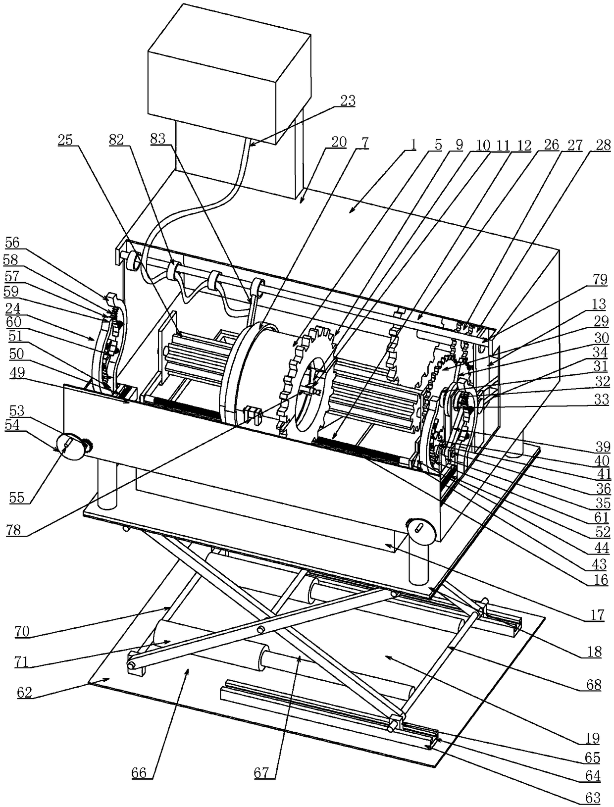
[0032] Embodiment one, combined with the attached Figure 1-11 , an orthopedic care cleaning device, comprising a box body 1 with an open upper end, the box body 1 is rectangular, and the side walls of the box body 1 have different heights, which can be set according to actual needs, and it is characterized in that the inner bottom surface of the box body 1 is along the There are two sets of first sliding rails 2 arranged in parallel at intervals connected to the front and rear direction, refer to the attached Figure 8 Two groups of first slide rails 2 are arranged in parallel at intervals along the left and right directions. The rail 2 and the bottom surface of the box body 1 form an inverted T-shaped cavity, and a first slider 3 is slidably fitted between the two groups of the first slide rails 2, so that the first slider 3 can only move along the first slide rail 2. move along the length direction, refer to the attached Figure 5 , the cross-section of the first slider 3...

Embodiment 2

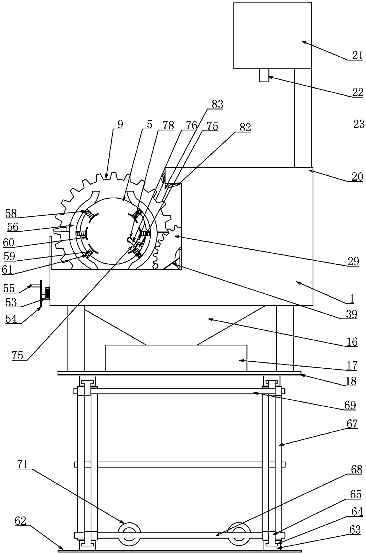
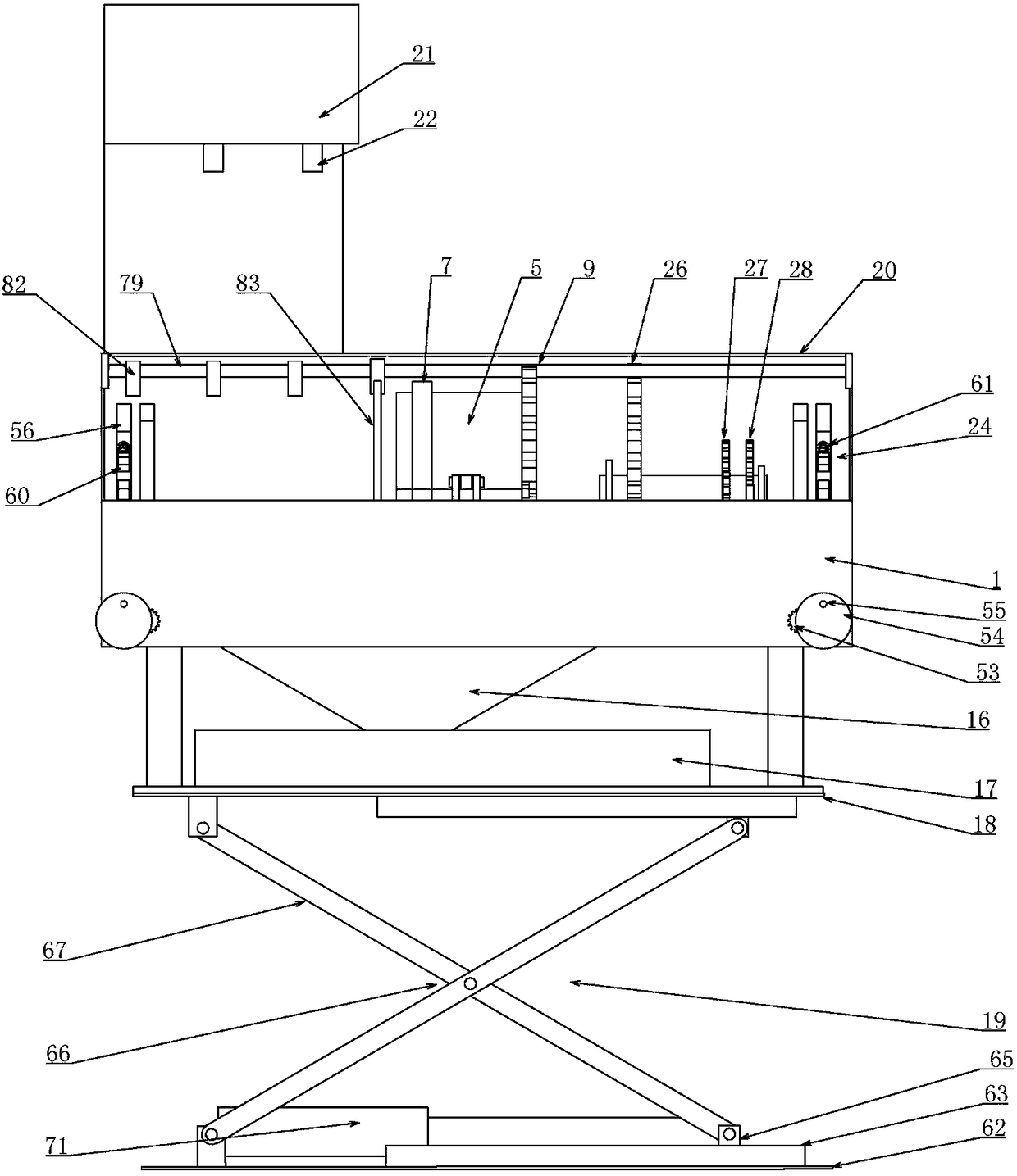
[0037] Embodiment two, on the basis of embodiment one, in conjunction with the attached Figure 1-11 , the driving device 13 includes a long gear 25 that is connected in the box body 1 and placed on the right side of the cylinder 5 in a forward and backward direction, and the long gear 25 satisfies that when the cylinder 5 moves along its axial direction, it is always Keep meshing with the outer ring gear 9, the length of the long gear 25 should be consistent with the moving range of the cylinder 5, because the cylinder 5 still needs to mesh with the outer ring gear 9 when moving in the front and rear direction, so the long gear The length of 25 will be set long enough, and also includes the first gear 26 that is placed on the right side of the long gear 25 and meshed with the long gear 25 and is connected in the casing 1 along the front and rear directions. The front end of the first gear 26 is the same as The shaft is connected with a second gear 27 and a third gear 28 in tu...

Embodiment 3

[0038] Embodiment three, on the basis of embodiment two, in conjunction with appended Figure 1-11 The transmission device 35 includes a transmission shaft 36 that is connected to the upper end of the box body 1 and placed on the left side of the main shaft 32 in a front-rear direction. The transmission shaft 36 is coaxially connected with a first pulley 37 and also includes The shaft is connected to the second pulley 38, and a first belt 39 is sleeved between the first pulley 37 and the second pulley 38. The setting of the first belt 39 here can transmit the power of the main shaft 32 to the transmission shaft 36, so The rear coaxial center of the transmission shaft 36 is provided with a fifth gear 40 rotatably connected to the upper end of the casing 1, and a third clutch 41 is connected between the rotating shaft of the fifth gear 40 and the transmission shaft 36, and the third clutch 41 is connected to the transmission shaft 36. There is a control system, the control syste...


PUM


Abstract

The invention relates to an orthopedic nursing cleaning device. Due to two covered cylinders, a diseased limb is cleaned, a water outlet nozzle is arranged on each cylinder, a buffer device is arranged inside a clamping device in the front-back direction of each cylinder, the diseased limb is well positioned and fixed, and no harm is caused to the diseased limb; a driving device drives the cylinders to achieve front-back feeding and rotation, thorough cleaning work is provided for the patient, a bed is prevented from being contaminated, a sector gear and a clutch device are introduced into thedriving device, a third gear and a fifth gear are alternately meshed through the sector gear, the cylinders rotate after front-back feeding is completed, and therefore the diseased limb is comprehensively cleaned, the open-close state of the clutch is controlled, the cylinders can rapidly reach the designated portion according to the need of a user to be repeatedly cleaned, operation is convenient and easy, the cleaning effect is remarkable, work burdens of nurses are greatly lowered, gauze can be replaced on a roller for medicine replacement usage, and the device has dual purposes, and is convenient to use and practical.

Description

technical field [0001] The invention belongs to the technical field of orthopedic care, in particular to an orthopedic care cleaning device. Background technique [0002] Orthopedic surgery is a diagnostic and treatment subject in medical institutions. It is the general term for trauma and spinal surgery. Professional departments for the diagnosis and treatment of sexual deformities, brachial plexus injuries and nerve entrapment. Bone defect mainly includes two parts: bone defect and defect repair. Bone defect is a common disease in clinical doubt, and it is also one of the problems that are rich in orthopedic treatment. At present, the methods for treating bone defects include autologous bone and allogeneic bone transplantation, tissue engineering technology, gene therapy rejection method, growth factor, adjuvant therapy of physical therapy and so on. [0003] At present, patients with orthopedic trauma, especially those with leg fractures, should not move the wounded le...

Claims


Application Information

Patent Timeline
Patent Type & Authority Applications(China)
IPC IPC(8): A61M3/02A61G12/00
CPCA61G12/00A61G2210/10A61M3/0279A61M3/0287
Inventor 鲁花
Owner HENAN PROVINCE HOSPITAL OF TCM THE SECOND AFFILIATED HOSPITAL OF HENAN UNIV OF TCM
Why Eureka
Try Eureka