
Pyrohydrolysis flash separation device, pyrohydrolysis flash separation technology, pyrohydrolysis system and pyrohydrolysis technology

A separation device and thermal hydrolysis technology, which is applied in the direction of pyrolysis treatment of sludge, sludge treatment through temperature control, etc., can solve the problems of sludge discharge pump damage, limited application range, large pressure fluctuations, etc., to reduce vibration and improve The safety production factor and the effect of reducing pressure fluctuations

Pending Publication Date: 2018-11-20
HUNAN JUNXIN ENVIRONMENTAL PROTECTION CO LTD
View PDF0 Cites 6 Cited by
  • Summary
  • Abstract
  • Description
  • Claims
  • Application Information

AI Technical Summary

Problems solved by technology

[0002] High-temperature thermal hydrolysis is a pretreatment technology for anaerobic digestion, and high-temperature thermal hydrolysis + high-temperature anaerobic digestion treatment process is often used to treat sludge. However, the high-temperature thermal hydrolysis process exposes the following defects in the actual treatment process: (1 ) The steam distribution branch pipe of the pulping machine is easily blocked, the steam pressure release of the thermal hydrolysis reaction tank is not complete, and the sludge discharge is overpressured and overheated; (2) The pressure fluctuation of the thermal hydrolysis system is large during the pressure relief process, and the pipeline vibration is large; (3) Due to the high mud discharge temperature, the mud discharge pump is frequently damaged
In order to solve the above problems, if the thermal hydrolysis system proposed by the Norwegian CAMBI company is used in the existing thermal hydrolysis process, it is necessary to prepare a large-capacity flash separation tank. About 5 times the size of the reaction tank, the site occupied is relatively large, limited by the site, technology and funds, which makes it difficult to implement the thermal hydrolysis system proposed by the Norwegian CAMBI company, and its practical application range is also severely limited
In addition, the existence of the above-mentioned problems makes the existing thermal hydrolysis system unable to meet the actual needs, and there are limitations in use

Method used


Image

  • Pyrohydrolysis flash separation device, pyrohydrolysis flash separation technology, pyrohydrolysis system and pyrohydrolysis technology
  • Pyrohydrolysis flash separation device, pyrohydrolysis flash separation technology, pyrohydrolysis system and pyrohydrolysis technology
  • Pyrohydrolysis flash separation device, pyrohydrolysis flash separation technology, pyrohydrolysis system and pyrohydrolysis technology

Examples


Embodiment 1

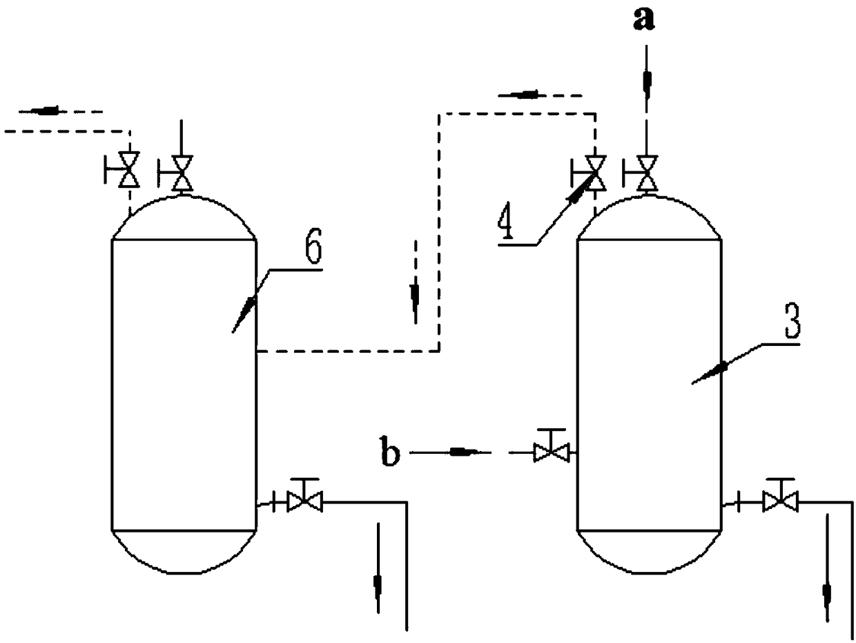
[0047] Such as figure 1 As shown, a thermal hydrolysis flash separation device includes a thermal hydrolysis reaction tank 3 and a gas-liquid separation tank 6. The thermal hydrolysis reaction tank 3 and the gas-liquid separation tank 6 are connected through pipelines, and the thermal hydrolysis reaction tank 3 The pipeline between the gas-liquid separation tank 6 is provided with a pressure relief valve 4 for regulating the pressure relief process of the thermal hydrolysis reaction tank 3, and the pressure relief valve 4 is arranged on the top of the thermal hydrolysis reaction tank 3, and the thermal hydrolysis reaction tank 3 It is equal to the volume of the gas-liquid separation tank 6.

[0048] In this embodiment, the sludge is transported to the thermal hydrolysis reaction tank 3. After reaching the design capacity standard of the thermal hydrolysis reaction tank 3, the relevant valves (including the pressure relief valve 4) are closed, and the sludge is transferred to t...

Embodiment 2

[0052] A kind of thermal hydrolysis flash separation process, adopts the thermal hydrolysis flash separation device in embodiment 1 to carry out flash separation, comprises the following steps:

[0053] (1) After the thermal hydrolysis reaction of the dewatered sludge in the thermal hydrolysis reaction tank 3 is completed, the opening and duration of the pressure relief valve 4 are controlled to regulate the pressure release process of the thermal hydrolysis reaction tank 3, which specifically includes three stages: Control the opening of pressure relief valve 4 to 30% for 180 seconds; control the opening of pressure relief valve 4 to 60% for 120 seconds; control the opening of pressure relief valve 4 to 100% for 600 seconds , thereby realizing the effective regulation and control of the pressure release process of the thermal hydrolysis reaction tank 3, and then effectively controlling the flash evaporation process of the thermal hydrolysis reaction tank 3, so that the feed li...

Embodiment 3

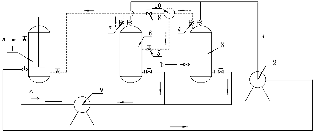
[0057] Such as figure 2As shown, a thermal hydrolysis system includes a slurry tank 1, a mud inlet pump 2, a thermal hydrolysis reaction tank 3, and a gas-liquid separation tank 6 connected end to end through pipelines, and the thermal hydrolysis reaction tank 3 and the gas-liquid separation tank The pipeline between 6 is provided with a pressure relief valve 4 for regulating the pressure release process of the thermal hydrolysis reaction tank 3, and the pressure relief valve 4 is arranged on the top of the thermal hydrolysis reaction tank 3, and the thermal hydrolysis reaction tank 3 and the gas-liquid separation tank 6 The volumes are equal, the pipeline between the pressure relief valve 4 and the gas-liquid separation tank 6 is provided with a first shut-off valve 5, and the pipeline between the gas-liquid separation tank 6 and the slurry tank 1 is provided with a second shut-off valve 7, The second shut-off valve 7 is arranged on the top of the gas-liquid separation tank ...


PUM


Abstract

The invention discloses a pyrohydrolysis flash separation device, a pyrohydrolysis flash separation technology, a pyrohydrolysis system and a pyrohydrolysis technology. The pyrohydrolysis flash separation device comprises a pyrohydrolysis reaction tank and a gas-liquid separation tank which are communicated through a pipe, wherein a pressure relief valve is arranged on the pipe therebetween. By the pyrohydrolysis flash separation technology, the pyrohydrolysis flash separation device is used for flash separation. The pyrohydrolysis system comprises a slurrying tank, a mud inlet pump, the pyrohydrolysis reaction tank and the gas-liquid separation tank which are sequentially communicated end to end through pipes; the pressure relief valve is arranged on the pipe between the pyrohydrolysis reaction tank and the gas-liquid separation tank. By the pyrohydrolysis technology, the pyrohydrolysis system is used for pyrohydrolysis. The pyrohydrolysis flash separation device and the pyrohydrolysis system have the advantages of small floor area, low production cost, a high safety production factor and the like, and the pyrohydrolysis flash separation technology and the pyrohydrolysis technology have the advantages of a simple process, easy operation, high treatment efficiency, a good gas-liquid separation effect and the like, so that actual treatment needs can be met and an application prospect is very good.

Description

technical field [0001] The invention belongs to the field of sludge treatment, and relates to a thermal hydrolysis flash separation device, a thermal hydrolysis flash separation process, a thermal hydrolysis system and a thermal hydrolysis process. Background technique [0002] High-temperature thermal hydrolysis is a pretreatment technology for anaerobic digestion, and high-temperature thermal hydrolysis + high-temperature anaerobic digestion treatment process is often used to treat sludge. However, the high-temperature thermal hydrolysis process exposes the following defects in the actual treatment process: (1 ) The steam distribution branch pipe of the pulping machine is easily blocked, the steam pressure release of the thermal hydrolysis reaction tank is not complete, and the sludge discharge is overpressured and overheated; (2) The pressure fluctuation of the thermal hydrolysis system is large during the pressure relief process, and the pipeline vibration is large; (3) ...

Claims


Application Information

Patent Timeline
IPC IPC(8): C02F11/18C02F11/10
CPCC02F11/10C02F11/18
Inventor 朱文
Owner HUNAN JUNXIN ENVIRONMENTAL PROTECTION CO LTD
Learn More