
SLAM system based on multi-view panoramic inertia navigation

A panorama and panorama image technology, applied in image data processing, instrumentation, calculation, etc., can solve problems such as large influence of scale estimation, limited and insufficient field of view, improve accuracy and robustness, realize deviceization, The effect of ensuring sufficiency

Pending Publication Date: 2018-11-20
安徽云能天智能科技有限责任公司
View PDF15 Cites 15 Cited by
  • Summary
  • Abstract
  • Description
  • Claims
  • Application Information

AI Technical Summary

Problems solved by technology

Monocular SLAM uses a single camera with a limited field of view. In addition, it is impossible to directly measure the distance of scene features, such as the Chinese patent "Monocular Visual SLAM Algorithm Based on Semi-Direct Method and Sliding Window Optimization" with application number 201710658521.X; binocular SLAM can calculate the scale according to the rigid constraints between cameras, but the accuracy largely depends on the calibration value of the binocular extrinsic parameters; RGBD-SLAM can obtain depth data in real time, but the limitations of the method limit the short-distance perception. For example, the application number is 201710835285.4 Chinese patent "A Kinect-based Visual SLAM Method for Indoor Mobile Robots"
None of the above systems and patents solve the problem of limited field of view, and cannot be applied to weak texture environments. At the same time, when the vision is degraded (motion blur, large scenes), the scale estimation has a greater impact, resulting in problems such as reduced system accuracy.
[0005] Therefore, how to provide a stable and reliable visual SLAM system to solve the insufficiency of information acquisition and the uncertainty of rapid rotation in the prior art environmental perception methods, and to ensure the accuracy and stability of the visual SLAM system has become an art field. technical issues to be resolved

Method used


Image

  • SLAM system based on multi-view panoramic inertia navigation
  • SLAM system based on multi-view panoramic inertia navigation
  • SLAM system based on multi-view panoramic inertia navigation

Examples


Embodiment 1

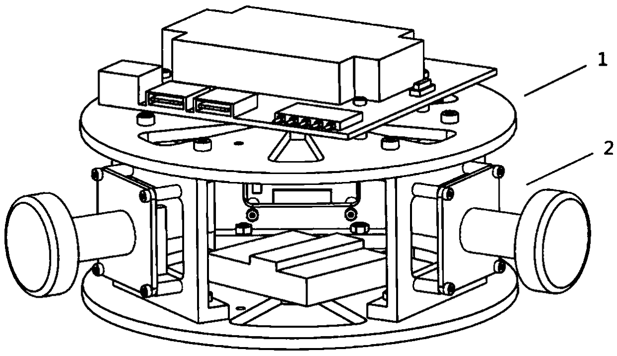
[0027] This embodiment provides a SLAM system based on panoramic inertial navigation, please refer to figure 1 , which is a schematic diagram of the structure of the trinocular panoramic inertial navigation SLAM system. Such as figure 1 Described, described trinocular panoramic inertial navigation SLAM system comprises embedded heterogeneous computing module 1, information collection module 2 and SLAM processing module (referring to Figure 4 ).

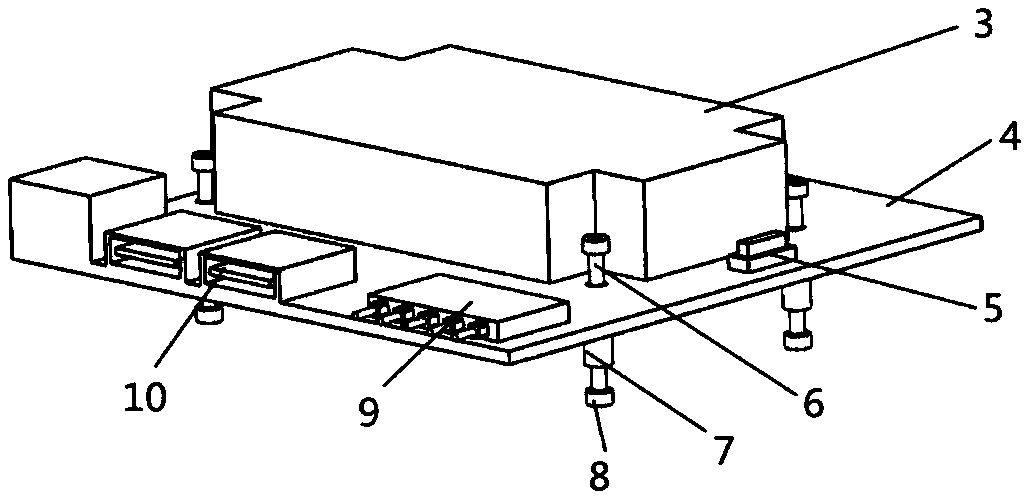
[0028] The embedded heterogeneous computing module 1 is used to control the hardware trigger circuit and SLAM algorithm acquisition and calculation. The embedded heterogeneous computing module such as figure 2As shown, it mainly includes a core processing module 3 , a function expansion carrier board 4 , a control switch 5 , a synchronous trigger hardware circuit 9 and an information input port 10 . The core processing module and function expansion carrier board meet the embedded heterogeneous mode and support ARM / GPU / DSP / FPGA i...


PUM


Abstract

The invention discloses a SLAM system based on multi-view panoramic inertia navigation. A 360 panoramic vision model is constructed, the high-precision vision SLAM and space movement tracking are realized through lightweight-level embedded parallel computation by combining the inertia navigation to closely couple and fuse with the vision feature, the problem that the environment sending method isinsufficient in information acquisition and uncertain in fast rotation in the prior art is solved, and an effective automatic measure is provided for robot environment modeling and positioning navigation in strong light / weak texture / movement fuzzy and like complex environments. The system precision and robustness are improved, the sufficiency of the autonomous navigation of the robot is guaranteed, and the lightweight and the device can be realized through the design way of the embedded system.

Description

technical field [0001] The invention belongs to the field of computer vision detection, relates to a SLAM system of visual perception, in particular to a SLAM system based on multi-eye panoramic inertial navigation. Background technique [0002] With the rapid development of artificial intelligence, robotics, unmanned vehicles, virtual reality, augmented reality and other fields have become research hotspots, especially when the environment is unknown and GPS signals cannot be used, it is the core of this field to realize precise positioning and create maps autonomously. research premise. Simultaneous Localization and Mapping (SLAM) refers to the method that the mobile platform uses the body or external sensors to perceive and construct a consistent environment map when the pose is unknown, and at the same time determine its own relative pose. SLAM is the key to realizing the autonomy of mobile platforms. In recent years, it has shown great application value in many fields....

Claims


Application Information

Patent Timeline
IPC IPC(8): G06T7/80G06T7/70G06T3/00
CPCG06T7/70G06T7/80G06T3/047
Inventor 刘勇张文张超凡王凡夏营威
Owner 安徽云能天智能科技有限责任公司
Learn More