
Switch reluctance machine system for new energy internet

A switched reluctance motor and Internet technology, applied in the direction of wind power generation, AC network circuit, DC power supply parallel operation, etc., can solve the problems of motor power density, performance degradation of power generation efficiency, large size and heavy weight of the motor, and achieve good economy The effect of feasibility and applicability, good low-speed performance and simple structure

Pending Publication Date: 2018-11-20
安徽怡咖电气科技有限公司
View PDF0 Cites 2 Cited by
  • Summary
  • Abstract
  • Description
  • Claims
  • Application Information

AI Technical Summary

Problems solved by technology

However, its control is difficult, and its power density and power generation efficiency are low at low speeds, which limits its further development in new energy Internet systems.
[0004] Poor output voltage regulation performance of permanent magnet generator system
In the case of high speed, the field weakening control cannot be realized, and the terminal voltage is prone to rise sharply, the insulation of the motor winding is damaged, and the motor is burned.
As time goes by and the ambient temperature rises, the permanent magnet will demagnetize, resulting in a decrease in the power density and power generation efficiency of the motor, making it difficult to exert its best performance in harsh environments
[0005] Electric excitation synchronous motors need to be equipped with excitation devices, and the rotor has excitation windings. The motors are generally large in size and heavy in weight, which increases the system cost and is not suitable for new energy Internet systems.

Method used


Image

  • Switch reluctance machine system for new energy internet
  • Switch reluctance machine system for new energy internet
  • Switch reluctance machine system for new energy internet

Examples


Embodiment Construction

[0026] The present invention will be further described below in conjunction with accompanying drawing:

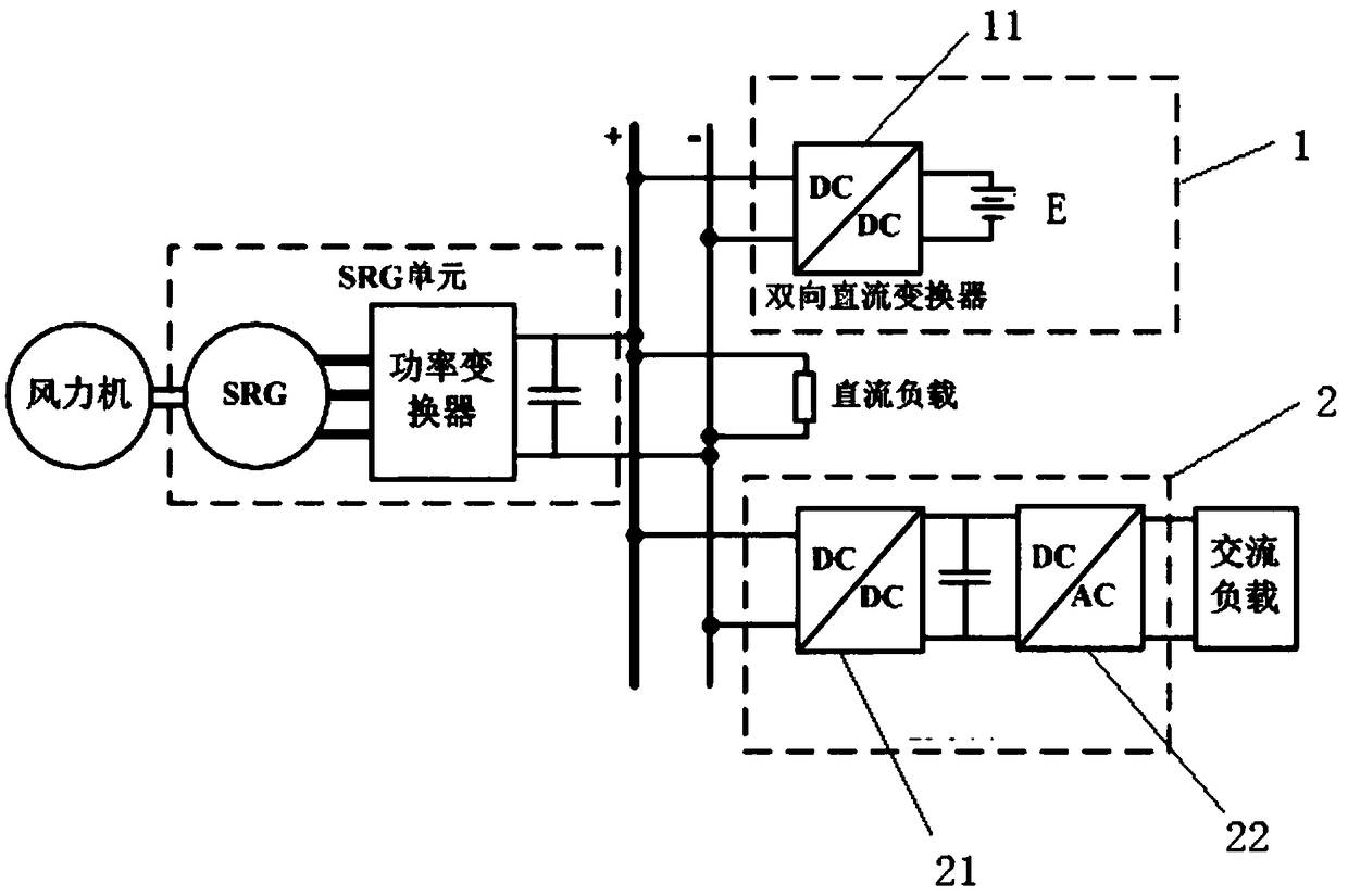
[0027] like figure 1 As shown, the switched reluctance motor system of the new energy Internet in this embodiment includes a switched reluctance generator unit connected between the wind turbine and the DC bus, an energy storage unit connected between the DC bus and the battery pack, and An inverter unit connected between the DC bus and the AC load.

[0028] The switched reluctance generator unit includes a switched reluctance generator and a power converter, which provide electric energy for the entire system. to the DC bus to supply power to other units in the system.

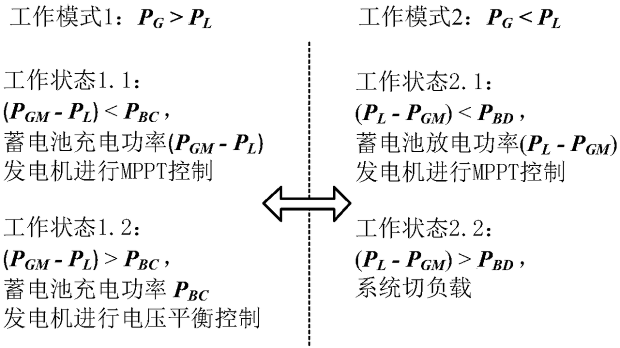
[0029] The energy storage unit includes a bidirectional DC / DC converter and a battery pack, the input end of the bidirectional DC inverter is connected to the DC bus, and the output end is connected to the battery pack. Due to the great uncertainty of new energy, in an independently operated new energy ...


PUM


Abstract

The invention relates to a switch reluctance machine system for new energy internet. The switch reluctance machine system for new energy internet comprises a bidirectional DC / DC converter and an inversion unit, wherein the bidirectional DC / DC converter is connected between a DC bus and a storage battery pack, the inversion unit is connected between the DC bus and an AC load, an input end of a bidirectional DC inverter is connected with the DC bus, an output end of the bidirectional DC inverter is connected with the storage battery pack, the inversion unit comprises a front-stage DC / DC boost conversion circuit and a post-stage DC / AC inversion circuit, an input end of the front-stage DC / DC boost conversion circuit is connected with the DC bus, and an output end of the front-stage DC / DC boostconversion circuit is connected with the AC load via the DC / AC inverter. The switch reluctance machine system for new energy internet can be used for a DC load and the AC load, energy is stored by astorage battery when electric quantity is sufficient, the energy is provided by the storage battery when the electric quantity is insufficient, and energy flowing in the system is achieved.

Description

technical field [0001] The invention relates to a reluctance motor system, in particular to a switched reluctance motor system used for the new energy Internet. Background technique [0002] The new energy Internet system has great development prospects. It is a powerful supplement to clean energy in solving the problem of electricity consumption by residents in remote areas without electricity. It has good application prospects in areas where large-scale wind power and photovoltaic power generation cannot be extended. , can be regarded as one of the effective, economical and feasible ways. With the advancement of motor technology and power electronics technology, alternators have become the mainstream models of new energy Internet systems, mainly including doubly-fed induction generators, permanent magnet generators and electric excitation synchronous motor generators. [0003] The doubly-fed induction generator system uses a power electronic converter to control the rotor...

Claims


Application Information

Patent Timeline
Patent Type & Authority Applications(China)
IPC IPC(8): H02J1/10H02J1/14H02J3/38H02J3/32
CPCH02J3/382H02J3/386H02J1/10H02J1/14H02J3/32Y02E10/76
Inventor 陈滋健陈昊王星
Owner 安徽怡咖电气科技有限公司
Learn More