Material delivery mechanism of aluminum template automatic blanking production line

A transmission mechanism and production line technology, applied to other manufacturing equipment/tools, metal processing, manufacturing tools, etc., can solve the problems of increasing the complexity of the equipment manufacturing process, requiring high machining accuracy, and complex structure of the lifting device, etc., to achieve structural The effect of simplicity, low inertia, and low consumption of mechanical materials

Inactive Publication Date: 2018-11-23
杜宗英
View PDF5 Cites 6 Cited by
  • Summary
  • Abstract
  • Description
  • Claims
  • Application Information

AI Technical Summary

Problems solved by technology

[0006] 2) Clamp rod A is a long cantilever rod, and it is still a necessary part. Sawing machines and punching machines generally need to be equipped with safety shields. The racks that drive the sawing machine feed trolley and the punching press feeding trolley cannot be configured on the sawing machine or punching machine. , if you want to push the material over the sawing machine or punching machine to the front material channel, you can only use long rods to push it
[0009] 3) Since the mechanical structure of the above-mentioned middle clamp rod A and clamp assembly A is relatively heavy, a lifting device with a higher load-carrying capacity is used. The lifting device includes a vertical plate A, a linear guide rail pair B, a lifting cylinder bracket A, The lifting cylinder A and the lifting bending plate A, the vertical plate A is installed on the upper plane of the feeding slide A, one side of the vertical plate A is connected with the guide rail of the linear guide rail pair B, and the other side of the vertical plate A is equipped with a lifting cylinder bracket A, The lifting cylinder A is installed on the lifting cylinder bracket A, the lower end of the lifting curved plate A and the slider of the linear guide pair B are respectively connected to the side of the horizontal sliding plate A, and the upper end of the lifting curved plate A is connected to the piston rod of the lifting cylinder A Above, the middle part of the vertical plate A is provided with a vertical long hole A with an open upper end, and the upper end of the lifting curved plate A can move up and down in the long hole A; in a word, the structure of the lifting device is complicated, the manufacturing process is complicated, and the mechanical materials Many, high manufacturing cost
This increases the complexity of the equipment manufacturing process and increases the manufacturing cost
[0011] 5) The transmission mechanism of the feeding trolley for the sawing machine and the feeding trolley for the punching machine is a combination of gear and rack, and its manufacturing cost is relatively high, and its installation requires high machining accuracy, otherwise it cannot work normally

Method used


Image

  • Material delivery mechanism of aluminum template automatic blanking production line
  • Material delivery mechanism of aluminum template automatic blanking production line
  • Material delivery mechanism of aluminum template automatic blanking production line

Examples


Embodiment

[0058] Example: see Figure 1 to Figure 15 .

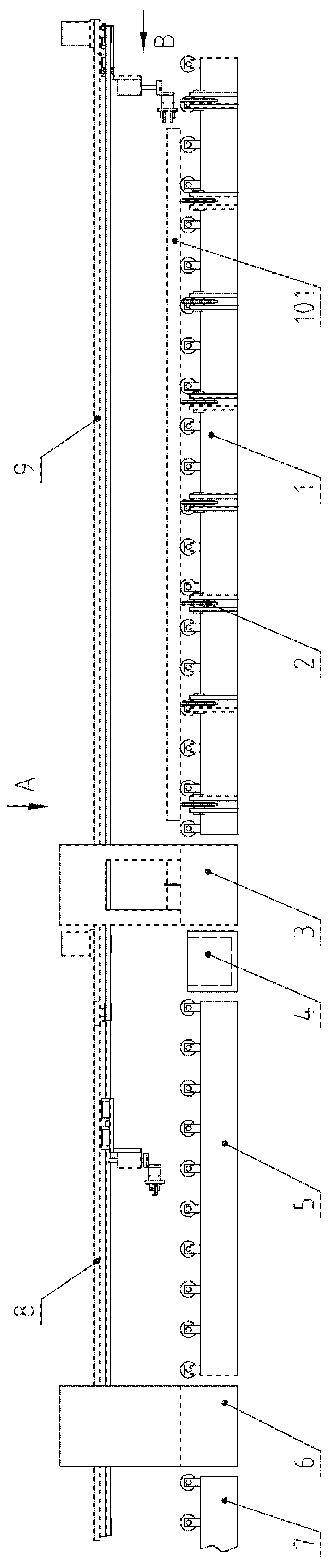
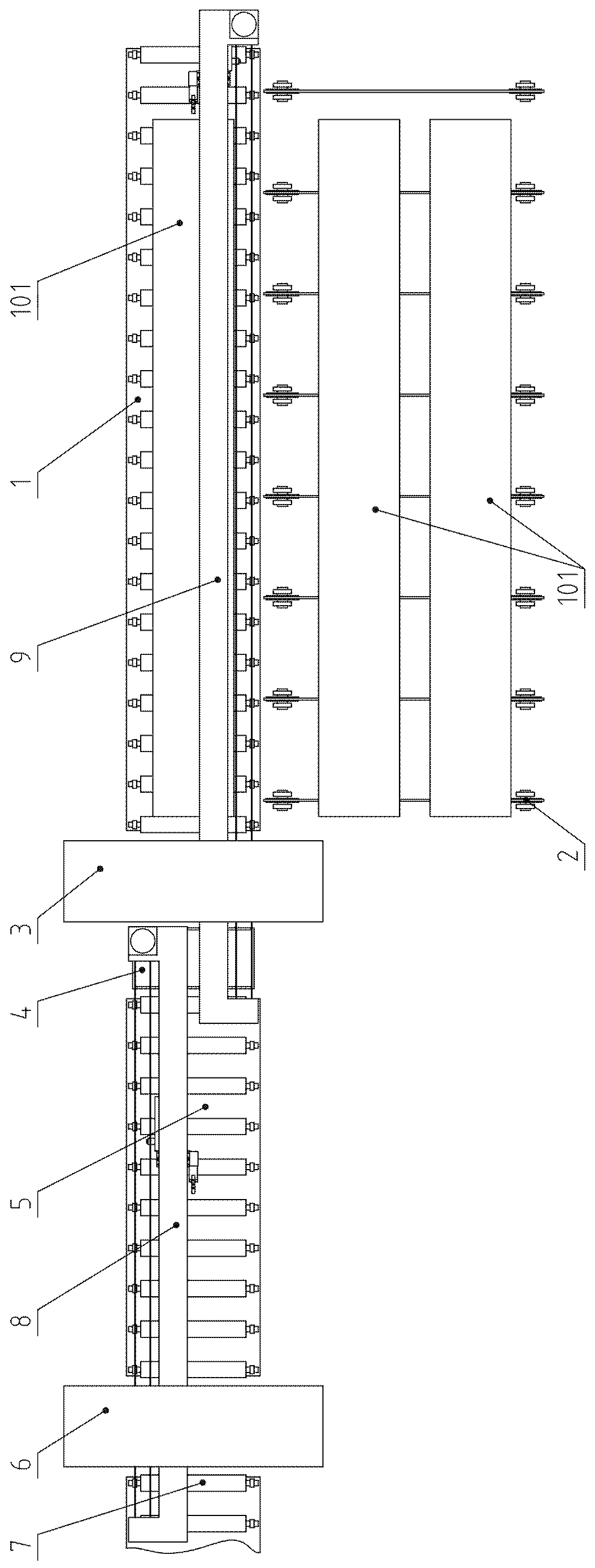
[0059] A material conveying mechanism for an automatic blanking production line of aluminum templates, including a feeder 8 for a sawing machine and a feeder 9 for a punching machine;

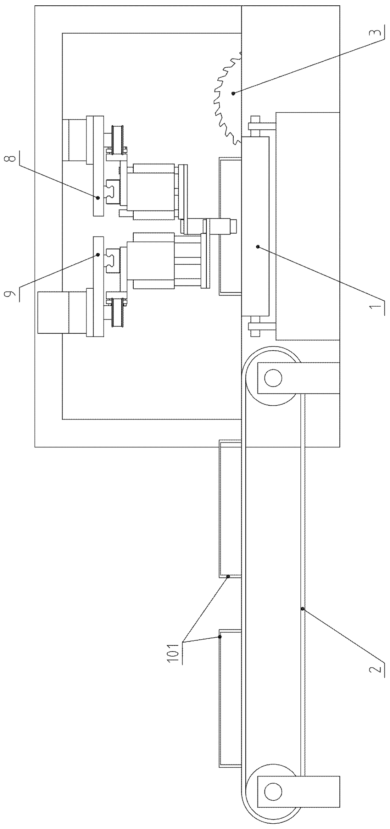
[0060] Such as Figure 12 , 13 As shown in and 14, the saw machine feeder 8 includes a support plate-81, a driving device-82, a driving synchronous wheel-83, a synchronous belt-84, a passive synchronous wheel-85, a translation assembly-86, and a guide rod type lifting cylinder- 87. Pneumatic finger one 88 and linear guide rail one 89; support plate one 81 is connected to the frame; driving device one 82 is a combination of servo motor one and reducer one; linear guide rail one 89 is fixedly installed on the lower part of support plate one 81, The linear guide rail one 89 is arranged in the front and rear horizontal direction; the passive synchronous wheel one 85 is connected with the support plate one 81 through the rotating pair, and the passiv...


PUM


Abstract

The invention belongs to the technical field of aluminum template manufacturing equipment and relates to blanking equipment of aluminum template blank materials and specifically relates to a materialdelivery mechanism of an aluminum template automatic blanking production line. a drive device I is electrified to rotate to drive a translation component I to translate forward along a linear guide rail; a guide rod type lifting air cylinder I drives a pneumatic finger I to descend; the pneumatic finger I clamps an aluminum template blank. A drive device II is electrified to rotate to dive a translation component II to translate forward along a linear guide rail II; a guide rod type lifting air cylinder II drives a pneumatic finger II to descend; the pneumatic finger II clamps an aluminum template. A sawing machine feeder and a punching machine feeder can realize relay delivery. The material delivery mechanism provided by the invention has the following beneficial effects: the delivery mechanism is remarkably simplified, and requirements on the manufacturing technology and machining accuracy are lowered while the feeding accuracy still can reach the using requirements and the manufacturing cost of the whole equipment is substantially reduced.

Description

technical field [0001] The invention belongs to the technical field of aluminum formwork manufacturing equipment, and relates to a blanking equipment for aluminum formwork blanks, in particular to a material transfer mechanism for an automatic production line for aluminum formwork blanking. Background technique [0002] The blank of the aluminum formwork is a relatively long aluminum profile. The first process of making the aluminum formwork is to saw the blank into multiple sections according to the requirements, and there must be a piece of leftovers about 50 to 100 mm at both ends. Holes then need to be punched in the sides of each sawn segment. [0003] The invention with the patent number CN201610518849.7 discloses a CNC sawing and punching integrated production line for aluminum formwork. Including sawing machine feeding device, sawing machine, sawing machine output and punching machine feeding device, punching machine, punching machine outlet, hydraulic system and el...

Claims


Application Information

Patent Timeline
Patent Type & Authority Applications(China)
IPC IPC(8): B23P23/04B23Q7/14
CPCB23P23/04B23Q7/141
Inventor 不公告发明人
Owner 杜宗英
Why Eureka
Try Eureka